
 Deutsche Version
Model railroad signal decoder
In the past few weeks I’ve built a model railroad signal for garden railways with a custom DCC decdoder. Here’s what it looks like:
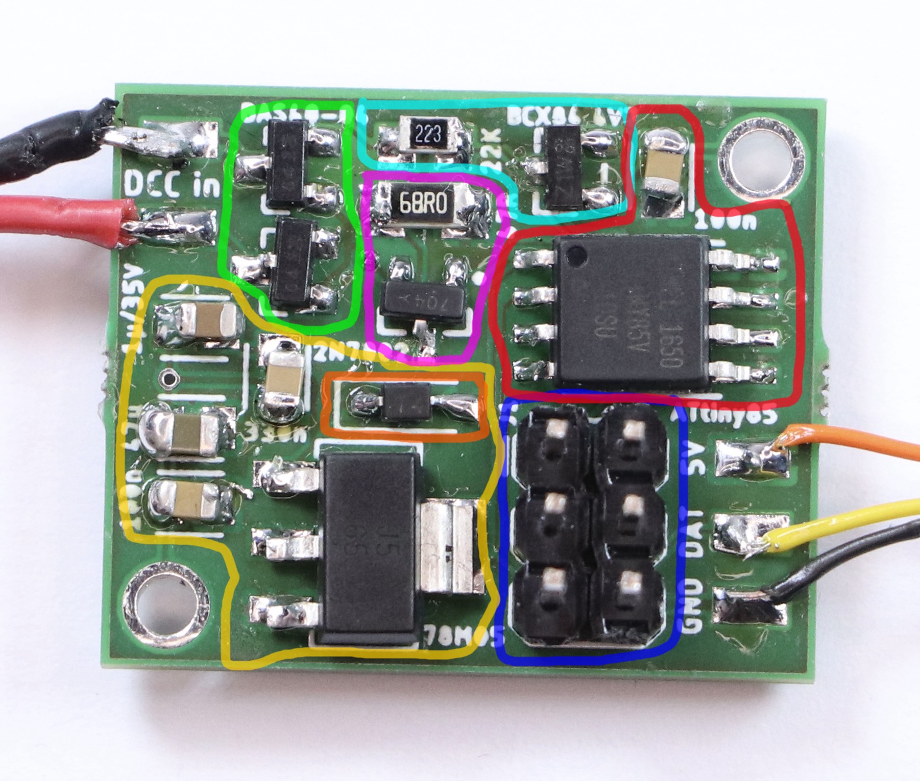
I’ve heard from a number of people that they thought this was interesting, but they didn’t really understand what I was doing. So today I’ll try to explain the core of it all, this circuit board:
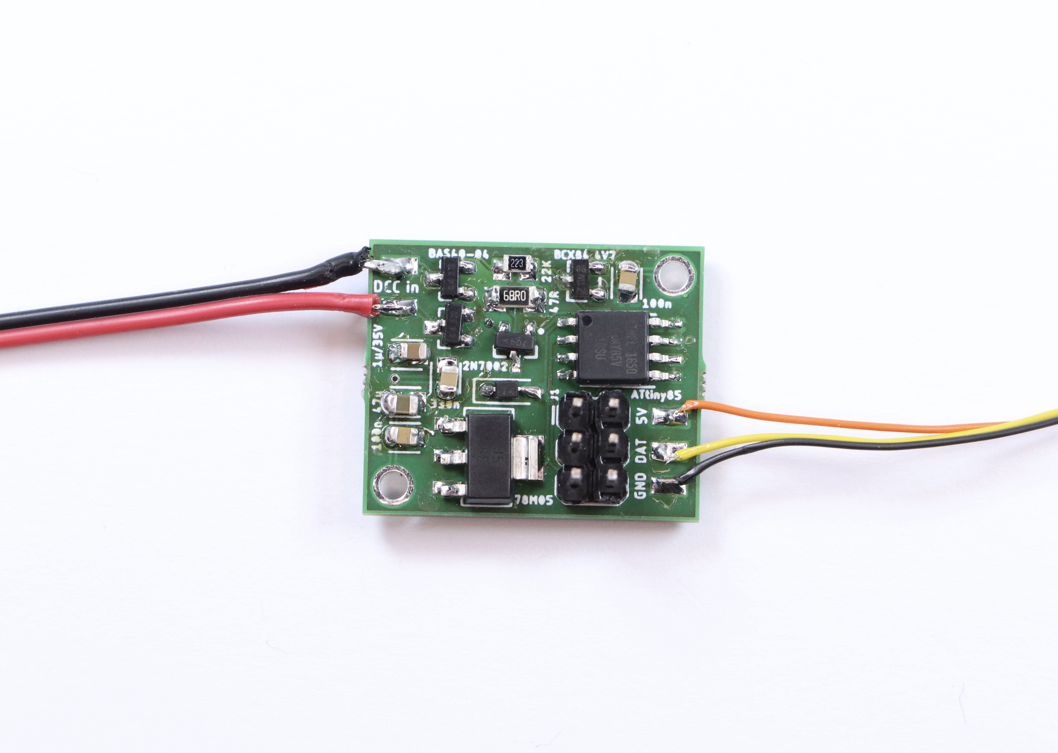
And here’s the associated circuit diagram:
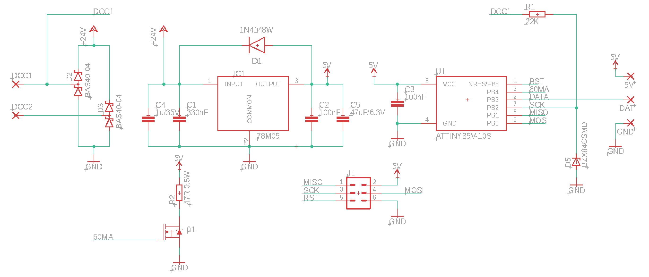
I’ll try to explain why this is the way it is and what it does.
(This whole explanation is aimed at people who have never done anything with electronics before. If that’s not you, then this may be a bit boring. Also, I didn’t come up with any of the parts of this. Most of this is based on things I learned by reading OpenDCC and Mikrocontroller.net. I’m sure I still made a lot of mistakes, though, and they’re definitely all mine and not the fault of anyone on these sites.)
The goal
First let’s talk about requirements. My goal was to build an american signal type “Searchlight”. Such a signal has between one and three lamps. Thanks to a clever electromechanic design that moves different color filters around, each lamp can show different colors - up to three from a total selection of four.
Replicating this system for a model railroad is not practical. I need something else. Having multiple colored LEDs next to each other wouldn’t work; they’re too big and I want it to all look like one light source. There are LEDs that contain red, blue and green in one housing, but that would require a lot of wires quickly that all have to be put in the mast. The solution is this:
![]()
This is an “adressable” LED, better known under the name “Neopixel” used by a large american online store. There are many variations from different manufacturers. The key thing is that each LED has a tiny control circuit built right in. It takes four wires: Plus five volts, minus, data in and data out. If you have more than one, you can connect the data out of the first directly to the data in of the second and so on. Connect the plus and minus as well, and you can control almost unlimited amounts of LEDs with just three wires.
The data line has a special protocol that you need to generate. Basically you need to switch it from 0 to 5 to 0 volts again and again at a certain rate; the time it stays at 5 volts (“high”) determines whether you’re sending a 0 or a 1. From these bits you form bytes, which tell each LED what specific color value to send.
Due to this dataformat, you definitely need some electronic circuit controlling the signal, and the first requirements for this are:
- Provide five volts DC power
- Generate the data for the LEDs in the correct format
The Input
There are a lot of options for designing the input side of things. In my case, I’m assuming the signal is electrically connected to the rails of a model railroad that is controlled digitally. With digital command control (DCC), the voltage at the rails has a constant value of about 15 to 25 volts, larger for larger scales. This voltage constantly flips polarity; first plus is on the left rail, then it goes to the right rail (and minus vice versa), and then back. It’s like AC in normal wall outlets, but with very abrupt changes instead of a smooth sine wave.
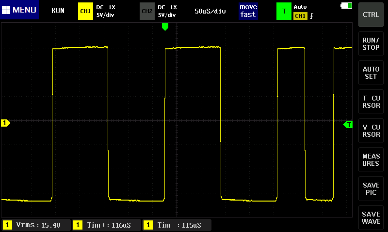
This voltage has two tasks. First it supplies the locomotives with power, but it also transmits information. If one of these change-and-back sequences is long, it transmits a “0”; if it’s short, it transmits a “1”. These bits together then form the bytes that form the messages that say things like, “Locomotive three run at speed step 64” or “switch 10 switch to direction left”.
This decoder uses both features. The digital voltage provides both the data and the power. For a locomotive, that is required since the only conductors you have are the rails. This is a stationary decoder, so I could have designed it so that it only uses digital commands, and gets the power from an external power supply. However, I wanted to use the least amount of cables, so I’m using the simple version.
With that, the requirements are fixed. The circuit has to:
- Turn the digital power (15-25 Volts, AC-ish) into 5 Volts DC
- Read and understand the digital data signal (decode it, hence the name “decoder”) and calculate the colors for the LEDs.
Computation
This calculation is the real key here. The digital signal has a completely different fromat than what the LEDs expect. It’s slower, but also has completely different meaning. At best it transmits “set switch or signal 10 to state 0”. Which color values are associated with that, let alone any blending to make it look nice, are things the signal has to decide for itself. There is no way to build a simple stupid adapter here; I need a complete computer.
Luckily, you can get those for cheap and in really tiny.

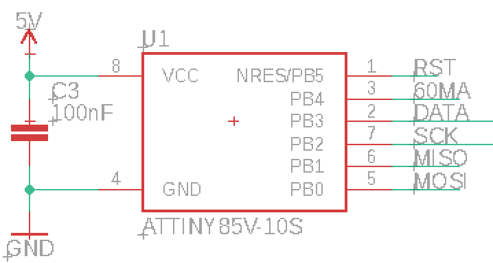
The ATtiny85 costs about 1€ depending on how many you order, and it’s smaller than one cent coin (I think in basically any currency), but from a technical point of view, it is essentially a full computer. It has all the important parts anyway. There is a CPU that can run at (depending on the version) up to 20 MHz; half a kilobyte of RAM and eight kilobyte of internal storage for the program. Multiple programs is a bit of a challenge. If you know Arduinos, the ATtiny85 is related to the ATmega328p in the Arduino Uno and Nano. Far less powerful, but cheaper and significantly smaller.
What it lacks are all the surroundings like keyboard and screen for input and output. The chip is designed for applications where this isn’t needed, or at least only minimal things. The software that you write can assign each pin (okay, five out of eight) freely for different tasks: The pin can work as an input, telling the software whether there’s a low or high level of voltage at it (meaning 0 or 5 Volts), or it can work as an output and write high or low values, meaning setting the pin explicitly to 0 or 5 Volts.
There are other options for the Pins as well; among other things it can also read analog voltages and generate them to some extent. But for this task I only need the simple digital high-low inputs and outputs.
These types of chips, known as microcontrollers, exist in thousands of variations by different manufacturers with very different performance characteristics. They are the key part of basically everything that’s digitally controlled these days. Washing machines, everything that plugs into a computer including every single Apple lightning cable, TVs, TV remotes, amazing amounts of parts in cars and so on are all the realm of microcontrollers. The ATtiny85 is, as the name implies, very much at the low end of the scale (though there are smaller ones), and even here, it is a bit out of date. But it is very easy to program and very forgiving of mistakes, which makes it great in hobby situations.
To run, this chip needs around 3-5 Volts DC (some versions like the one here can also run on a bit less) and exactly one capacitor. I’m already generating 5 Volts DC for the LEDs anyway, so this chip will get them as well. That means for all the calculation, only two pieces of hardware are required.

There is some more associated hardware, though, for getting the program (which I’ve written myself) on the chip. For that you need a programmer, a device that you can buy for some money, or make yourself astonishingly easily from an Arduino. It needs to be connected with six wires to the chip. The standard for this is with a six-pin plug, which I’ve thus included here as well. There are standard six-wire cables for this.
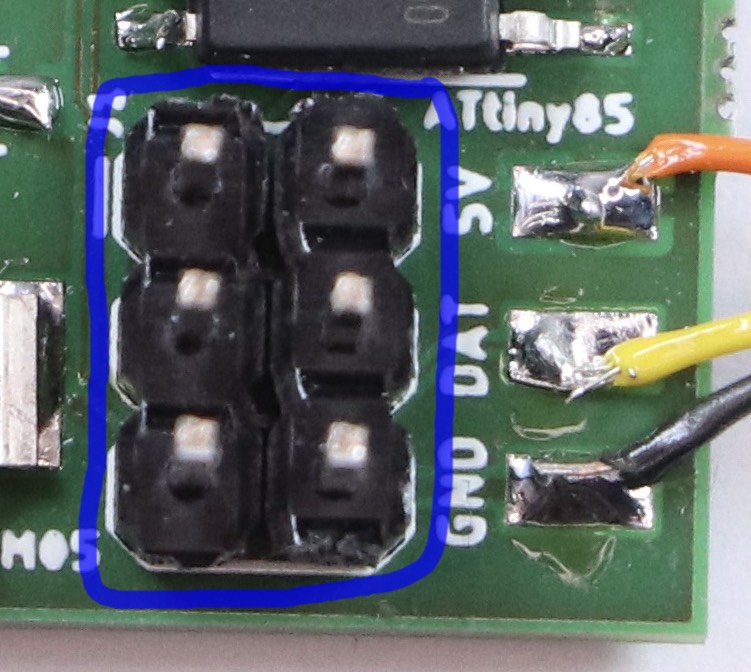
You could connect the cables differently, for example with some sort of spring-loaded contacts on some programming circuit board you’d have to build for that, or in the worst case, just temporarily solder the cables in there. But the plug version is both simple and convenient, with the only downside that it makes the circuit a bit more pointy.
5 Volt DC
The 5V DC is a fairly boring topic compared to the slightly complex software. But on the other hand, a lot of the circuit board is just concerned with it, and it is really the basis of the decoder. It fundamentally consists of two parts:
DC
To generate DC I’m using a bridge rectifier, a simple standard setup of four diodes.
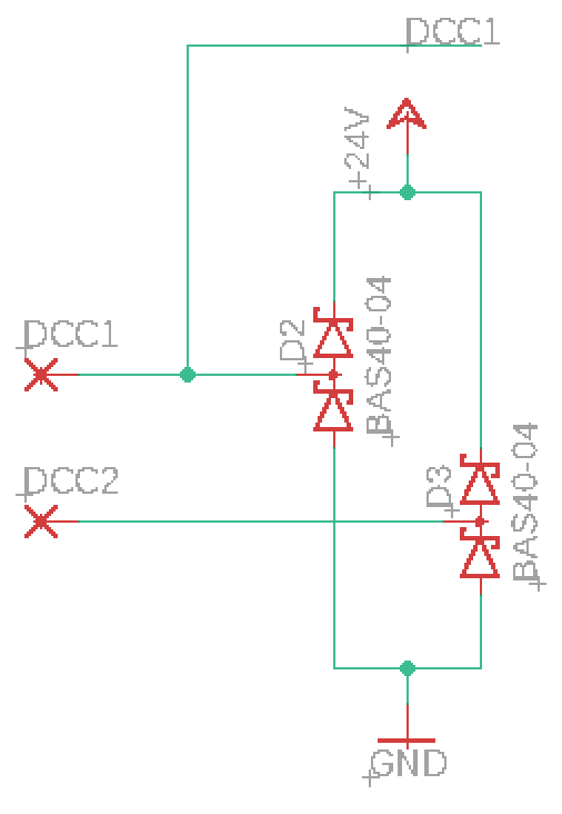
The diodes are arranged such that no matter what, the rail that is currently “plus” is connected with the internal “plus”, and the rail that is currently “minus” is connected to the internal “minus” (also known as ground, shortened to GND).
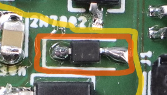
To simplify the circuit board I’m using double diodes. These are parts that contain two diodes in one housing. The diodes are connected with each other and the three pins.
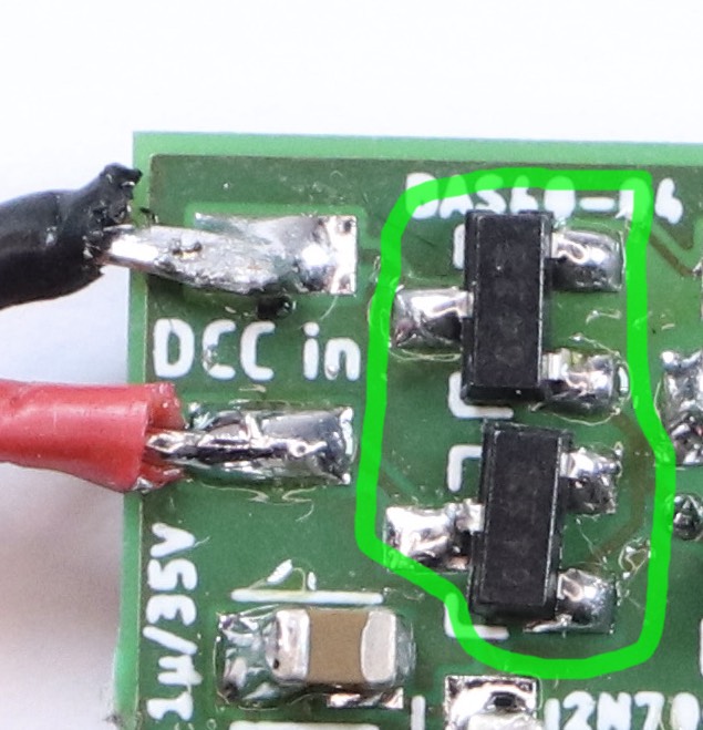
The first (here lowest) pin is connected to the cathode of the first diode. The middle pin is connected to the anode of the first diode and the cathode of the second. The top pin is connected to the anode of the first pin. That means I need only two parts to have four diodes. There are integrated bridge rectifiers you can buy, but those are optimized for normal AC and not ideal here.
5 Volt
From the rectifier we get between 15 and 25 volts DC, depending on what the model railroad is set to. Honestly, 25 is probably excessive, but I preferred to err on the side of safety. Either way, even the low end of the scale will immediately fry the small LEDs and the microcontroller. That means I need a voltage regulator.
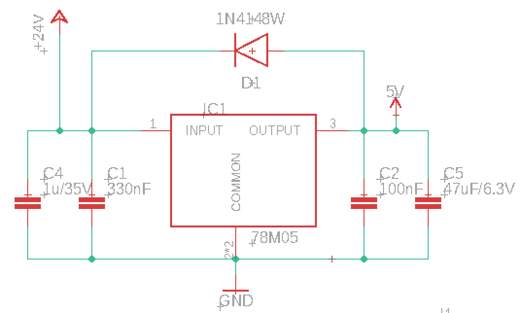

The voltage regulator, here an UA78M05, is a fairly complex integrated circuit that contains a big output transistor that conducts current. Part of the circuit checks whether the output voltage matches the expected 5 Volts; it opens or closes the transistor more or less to ensure it does. For stable working it needs a few more capacitors at both input and ouptut side.
An oddity in the design I’ve chosen is the diode.
During normal operations it is blocking, meaning it does nothing. You could totally get rid of it. The problem is when I program the microcontroller. In that case the 5V for the whole design comes from the programmer device. In that case the voltage regulator has 0 Volts on the input side and 5 Volts on the right. It does not like that and could be destroyed from that, since current is going the wrong way round in there. In this case the diode conducts the 5V (minus 0.7) to the left side. That is not enough for the regulator to do anything, but it is enough to ensure that it doesn’t break.
The specific diode, type 1N4148, is one I picked because I had some of those laying around.
The whole voltage regulator is a very simple solution, but not a great one. The very high-level view is that it works like a self-regulating resistor. That means the current going through it is the same on the input and output side, and only the voltage changes. If you get 5 Volts with 20 milliampere out, then you need to put 20 milliampere at, say, 15 Volt in. The difference of 10 Volts times 0.02 Ampere means you loose 0.2 Watts, which get turned into heat. That may not sound like much, but it already gets warmer than I expected. I think with up to three LEDs it should be alright, but there’s definitely room for improvement.
The preferred solution would be a so-called buck converter, a significantly more complex part that needs more additional components. I’m going to try that out for the next version of this decoder.
Data Input
To parse the DCC signal, it’s sufficient to read the data from a single rail. If the rail is the “plus” rail, it has a high voltage (compared to the internal Minus or 0 Volt level); if it is the minus rail, then it is connected via the rectifier to the internal 0 Volt level. Using just one input means I can’t tell the difference between “track is minus” and “there’s no power from the track”, but since the decoder is always wired in, I don’t think that’s important.
The problem is that when the track is positive, it has a voltage of 15 Volt compared to ground. That is way too much for the microcontroller. To solve this I’m using a small design with a Z-diode.
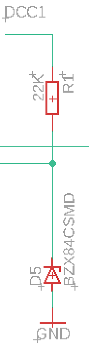
The special thing of a Zener diode is that if you put it in reverse, where normal diodes block, it will start conducting anyway if the voltage exceeds a certain level (and stop once it doesn’t anymore).Here I’m using a 4.7 Volt one. If the input has 4.7 volts or more, it starts letting so much current through that the voltage drop over it is pretty much exactly 4.7 Volts, which is enough to be read as “High” by the microcontroller.
The amount of current that the Zener diode lets through can quickly grow very high, which in turn can destroy the diode. That’s why it needs to have a fairly large resistor in the line leading up to it, to ensure that there is never a lot of current going through it. The microcontroller itself doesn’t need any current from this pin, it just measures whether the voltage is above or below a certain threshold. That way it can read the DCC signal.

A weird specialty here: Like all diodes, a Zener diode has only two ends that need to be connected. For some reason, the one I have here comes in a package that has three leads. (Yes, that is the same package as for the rectifier diodes.) The third lead isn’t connected to anything in the diode, and it isn’t connected to anything on the circuit board either. It’s just soldered in to hold the Zener diode safely in place. I’m not sure why it was designed this way, but at least it makes it impossible to solder it in the wrong way round.
Bonus: The decoder also works flawlessly if I just leave out the Zener diode and use only the resister. I’ve tested this. The excessive voltage gets transferred away via built-in protection dioes on the microcontroller which connect it to the 5V rail… somehow. I haven’t honestly really understood what’s happening in that case, and in particular how I calculate it. I know from the internet that somewhere between 22 and 33 kiloohms works well here, but I can’t actually show you the maths that prove why. That’s why I preferred to use the version with the Zener-Diode here, which is much more easily understandable. The next version of the decoder, which will get more components elswhere, will probably not have the Zener-diode though, just to save space.
Output
The output hardware for the microcontroller is simple because there is none. One pin of the controller is directly connected to the data in pin of the first LED.
There are Best-Practices documents for these LEDs that recommend adding a resistor, ideally close to the LED. Since I don’t have long leads to the LED and only use relatively few, I haven’t needed that this far. If I do, I’d probably add the resistor to the LED instead of the decoder.
That means the decoder is done. Well, almost.
Output part 2: Acknowledgement
A problem with classic digital model railroads is that the protocol is strictly one-directional. There is no way for the decoder to send any information back. No part of the circuit I’ve designed here can provide any voltage back to the tracks or similar.
Most of the time that’s no problem. But if a digitalsystem wants to configure the settings that the decoder has, for example setting the address it responds to, then it would be nice if there was a way to read the existing value, and get a signal that a new value has been written successfully. For that, there is a small hack: The decoder in a locomotive simply briefly turns on the locomotive’s motor. This increases the current drawn, and that can be measured.
The problem for my decoder is that there is no motor connected. So I need to increase the power draw some other way. In the first version I did that by simply turning the LEDs on fully white, which actually works. But there are scenarios where this might not be sufficient, for example if I build signals for N gauge with smaller LEDs that draw less power.
So that means I need to increase power by letting current flow through a resistor. The resistor needs a larger housing because it needs to withstand more power that gets dissipated in it. I guess one in a smaller housing would work just as well, since the power is applied only very briefly (six milliseconds), so it doesn’t really have the time to get hot, but better to err on the side of caution.

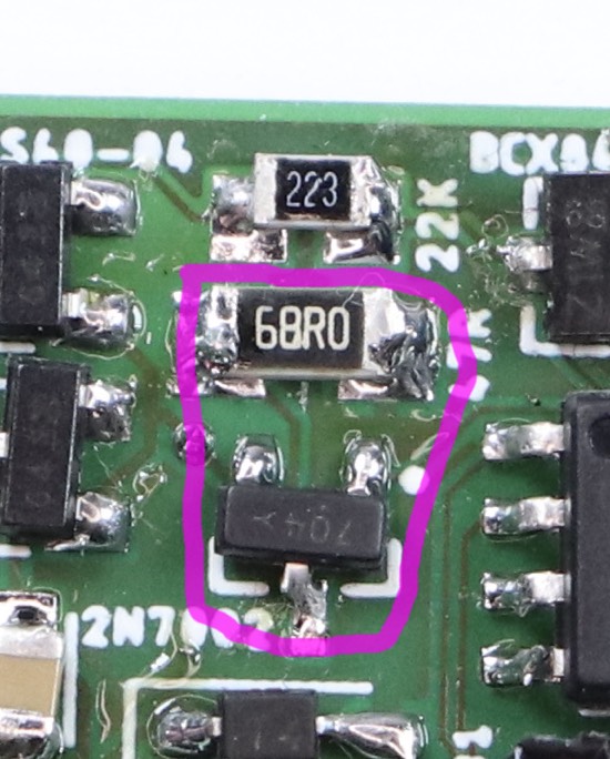
If you look closely you may see that the circuit diagram and the board both say 47 Ohm, but the resistor is actually 68 Ohm. I did the maths again and changed my opinion after I had alreaady ordered the circuit board here.
The resistor cannot be connected directly to the pin of the microcontroller, because the microcontroller can’t deal with all the current that would flow through it. Instead I’m using a small transistor, specifically a MOSFET of type 2N7002. This thing is nice and easy: If the microcontroller output pin is at 5 Volt, then it is open, if it’s at 0 Volt, then the transistor is closed. There is no additional hardware required.
The only real problem with this transistor is that it is the third different component in the same exact package. It is the same package, known as SOT-23, that is used by the Zener diode and the double diodes for the rectifier.
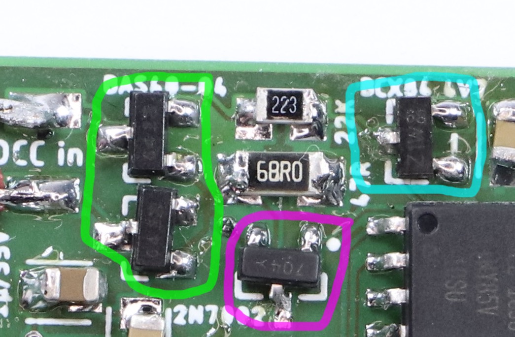
If you shine a lot of light on it, then you can maybe see that each of them has some markings. These markings are difficult to read under the best of circumstances, and they’re only a code for the component; you still have to look up which thing it actually is in a table somewhere. Really, what you should do is keep these pieces in the labelled plastic bags they came in until you need them, and then immediately put them back before you open the next bag.
(I deliberately ignored something here: There is a fairly complex extension of the DCC standard known as Railcom which decoders can use to answer. This requires additional hardware on the decoder, which I didn’t add, and also a more powerful microcontroller.)
Conclusion
That’s all there really is to this decoder. I’ve designed the circuit diagram and the board layout with Eagle. I wouldn’t say I really like the program, but it can do everything you need, and it’s free for hobby purposes. I did not make the circuit boards myself, but instead had them made at Aisler. They charge a little over six euros for three of these boards (size about 2 by 2.5 cm). I’ve soldered it together myself, and indeed, it happens to work.
Written on August 29th, 2021 at 12:43 pm