Blog

The Shapes of Railway Networks

I made this post on another site a while ago, and I really like it, so I thought I’d replicate it here. If you happen to know the original post, I couldn’t find the original images I had anymore, so I recreated them, and as a result they’re slightly different. But I think that shouldn’t matter to much.

The basic idea here is that you can tell a lot about a country and in particular its history during the 19th and early 20th century by its railway network. So let’s do that. And the best way to do that is by looking at the incredibly detailed open-source world railway map OpenRailwayMap, a part of the OpenStreetMap project. I really recommend it! Note, though, that some relevant rail lines aren’t shown at the zoom levels I’m using here, sometimes it’s a bit wonky. But anyway, let’s start with one of my favorite examples of how railway networks differ:

At this zoom level the site sadly only shows incomprehensible internal abbreviations rather than city names, so let me explain: What we have here are France and Germany, along with some of the UK and Italy, some of various neighbouring countries and all of Switzerland, Belgium and Luxembourg.

France and Germany are the ones that I find the most interesting, because the shapes of their networks are so different. Not only is the german one much more dense, but you can see completely different patterns.

In France, the job of railroads is to bring people to Paris (PLY, short for Paris Gare de Lyon) The lines stretch out into every part of the country, but almost all of them converge onto mainlines going into Paris. You can see some lines along the coasts and the borders, and there is a medium distances circle around Paris (passing MZ, DN, TO, short for Metz, Dijon, Tours). This whole pattern is known as the Legrande Star, after Baptiste Alexis Victor Legrande, the french government official who designed it. His goal was to provide great access to Paris, the nation’s undisputed political, cultural and economical centre. A couple of decades later, Charles de Freycinet added plans to connect all departments to the railway network, but he still followed the idea that the ultimate goal of almost every rail line was Paris. And so it was, and largely remained. Even the high speed lines, in red, follow this pattern to this day.

A result is that you will have to go to Paris whether you want to or not. Lille-Strasbourg? You’re going through Paris. Bordeaux-Dijon?

You’re going through Paris, and get to make your own way from Gare Montparnasse to Gare de Lyon on the Metro (and it isn’t even a direct metro, you have to change trains). It’s a massive detour but it’s not like you have a choice.

Even if there is a direct TGV or a connection outside the main stations of Paris, you’re still ending up very much near Paris; the difference is just that you’re not going via the city centre, but rather via Disneyland. Legrande wanted to bring people to Paris; he was less concerned about connecting other places with each other.

Now compare Germany, and you will see a network that is more dense, but most importantly, utterly chaotic. You can see hints of a France-like star around Berlin (BSPD, short for Berlin Spandau, which isn’t the most important station but what can you do), but it’s really only dominating its immediate surroundings, the region of Brandenburg. You can see vague hints of a similar star around Hamburg (AHAR; don’t ask) or Munich (MH), but also a massive tangle around the Rhine-Ruhr industrial area (around KD), or around the Frankfurt am Main area (FF). Red high speed lines are essentially random. Some of them do go to Berlin, sure. But many, like the one from Cologne to Frankfurt (KD to FF) or the one from Hanover (HH) south, do not.

And that really reflects the history. Germany wasn’t a unified country when railroad construction began, and even though it did unify shortly thereafter, there’s no hiding that its different parts developed separately, with no central planning, ever since the middle ages. Germany doesn’t have a single central city like France. Berlin is the biggest and most important city, but not by far. Hamburg has huge cultural and industrial influence, Frankfurt is the most important financial centre and airport, Munich is huge, and there are agglomerations like the Rhine-Ruhr region that used to beat all of them in terms of industry. And the rail network, with no single central focus point, reflects that.

That doesn’t mean Germany doesn’t have its own blind spots. Due to being split in two, the east-west links aren’t great. Getting e.g. from Cologne (near KD) to Dresden (DH) is pretty painful. Ironically, Berlin is one of the places that really suffers from this. There are plenty of trains to it from Cologne but they take forever, and you can see why: A lot of the route isn’t high speed, it’s just more or less upgraded normal lines. If you have a single destination, then it’s easy to build all the lines there. If you want high-speed connections between everything, that’s more difficult. (Also, our government isn’t investing anywhere near enough into the rail network, both compared internationally and on its own terms, but that’s a different issue)

Other countries in Europe tend to be somewhere between the extremes. Spain is fairly centralised around Madrid.

The UK is just as focused on London as France is on Paris, but it has strong regional networks around Leeds and Sheffield, and some weirdness in Scotland (four different lines between Glasgow and Edinburgh and counting!).

Italy, especially south of the Po valley, almost looks like a ladder: Lines are either on the one side of the Apennines or the other, with a few select ones crossing through, and a red high speed spine that finds its own axis in the middle.

This works overseas as well. Describing the continental US as “like Germany” is certainly going to raise some eyebrows, but the map doesn’t lie:

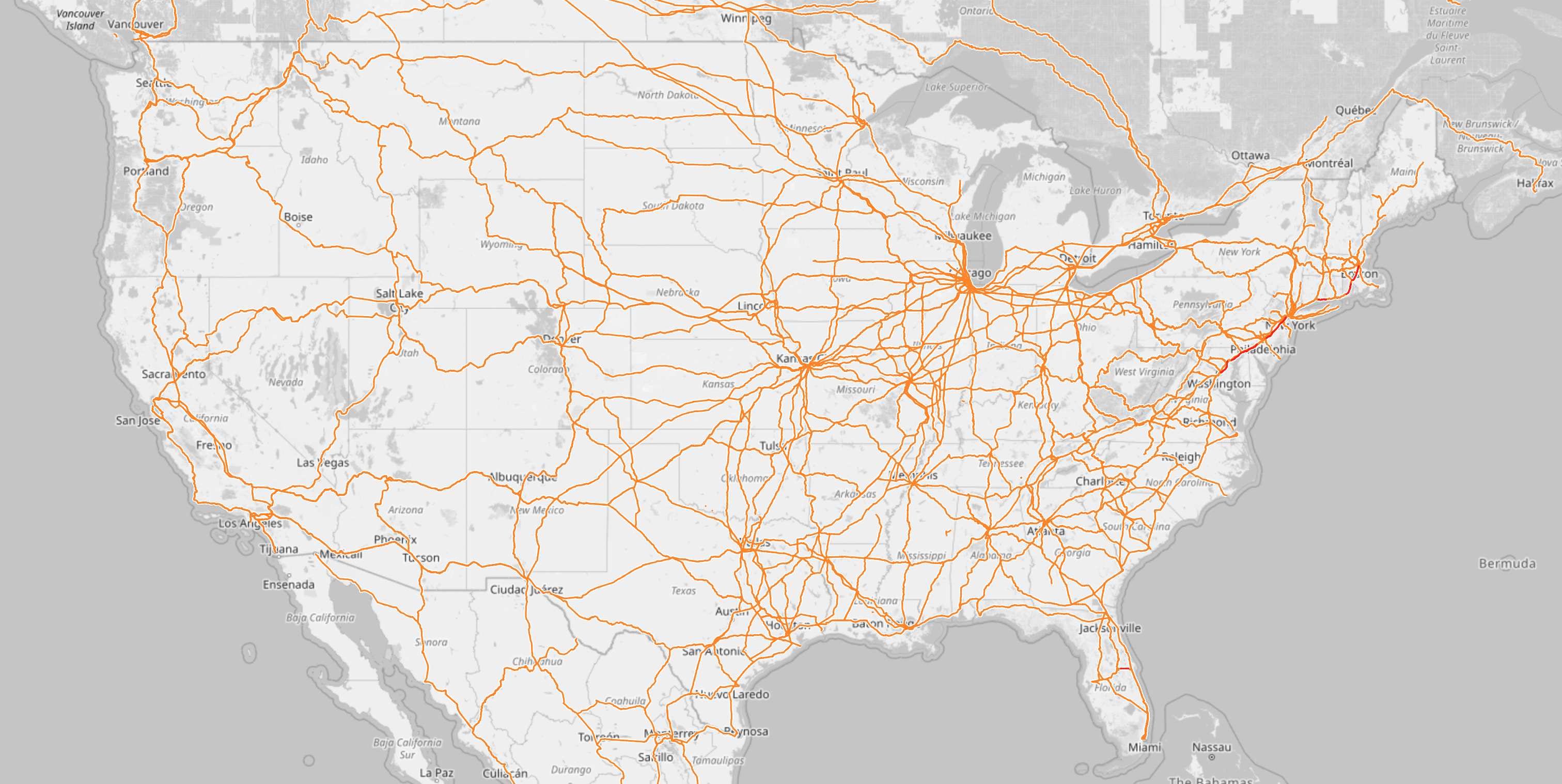
It’s all on a completely different scale, but it’s also a federal country with no one single clear centre. Yes, New York and Los Angeles are big and important, but neither is an all-powerful centre of the nation. What’s fun about the US is that it’s almost gradient-like: The more west you go, the fewer the railroads get. You can also nicely see the Alleghenies by the shadow they cast: Building lines through there or around them is expensive, so very few do. Other characteristic items are the huge tangle that is Chicago, the closest thing the US has to a railroad capital; and the many places where lines are almost duplicated (just count how many different ways you can get from Chicago to Memphis, or Chicago to Cleveland), thanks to different competing railway companies that all hated (and sometimes still hate) each other’s guts.

So that’s what’s mostly considered the “western world” or “industrialised world”. I skipped Japan, China and India because the post is going to get too long no matter what, but they’re all fascinating as well.

But if we go away from there look at countries where the colonialism was less settlers and more exploit mostly from afar, we see another very odd pattern emerge, like here in sub-saharan Africa:

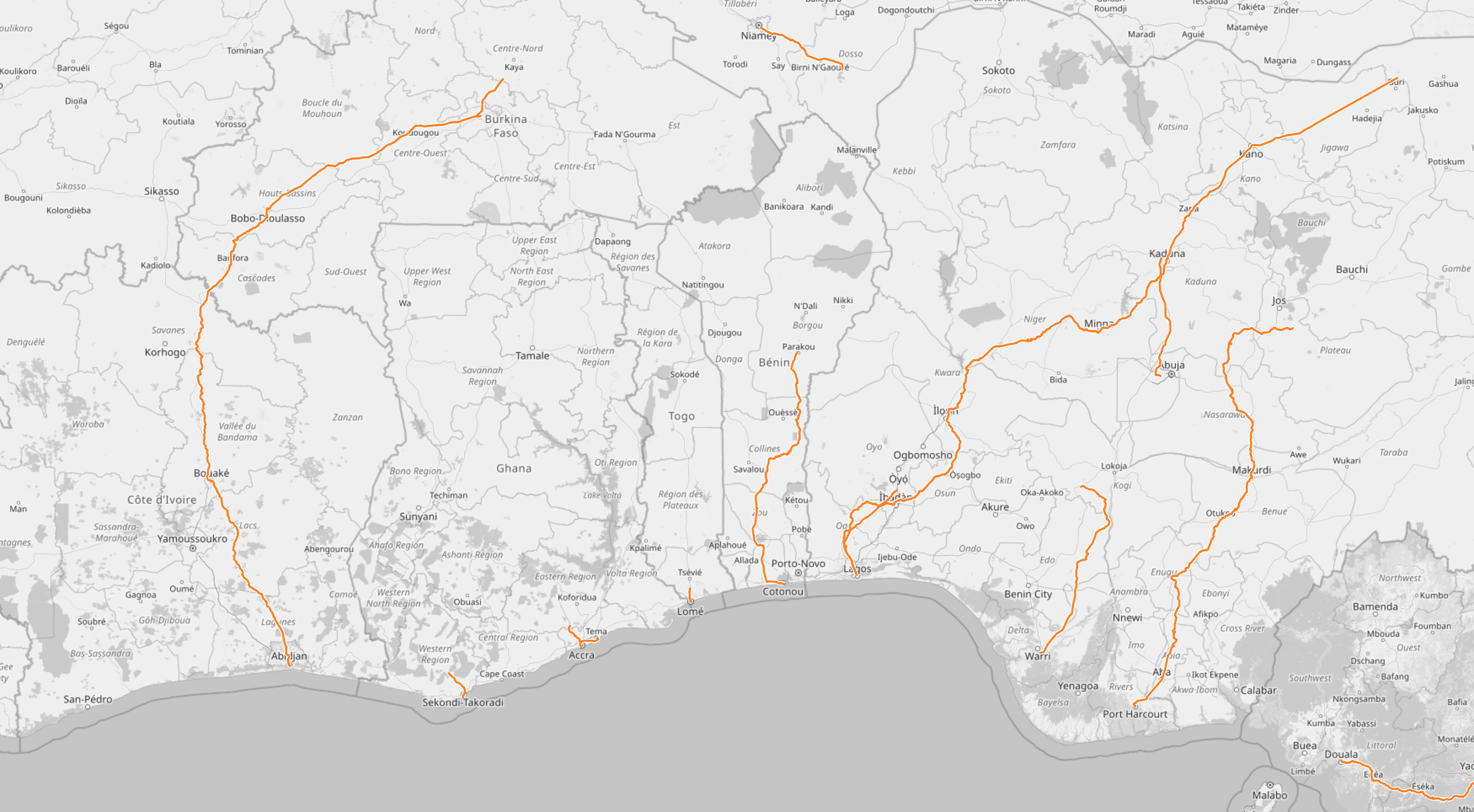
The selection is somewhat arbitrary because you can find the same pattern everywhere south of the Sahara, and in one case (Mauretania) even in the Sahara: A railroad that goes straight to the coast. Note that the isolated sections inland are due to issues with the map software, they’re all connected to one of the lines to the coast; and also some of them used to be longer when I made the original post earlier this year. If you zoom in, it’s all there, but apparently some of the lines are now disused.

This kind of railroad is designed to extract a country’s resources, and not much else. In Mauretania (not in this picture), that’s iron ore. Elsewhere it might have been other ores, precious metals, gemstones, but also very often agricultural products, spices, dyes. The railway line exists to take these things and bring them to a port. It is not designed to actually help the nation grow economically.

Think about it: All things being equal, you’re probably just as likely to want to go parallel to the coast as perpendicular to it, but the railways don’t facilitate that. Yes, coastal shipping is a thing, but loading things onto ships costs time and effort (aka money). Most more developed countries I’ve shown have lines that parallel coasts, either directly at the shore or a bit inland.

Also, each of these lines were built because there’s something interesting at the end of it, or at least someone suspected there might be. If you wanted to develop the area, it would make sense to trade the interesting stuff in Togo with the interesting stuff in Benin. But the railway lines are not set up for that at all. The goal is to get the interesting stuff to a ship, and occasionally soldiers to the place where the interesting stuff comes from.

These days, the area that I screenshotted here is actually a massive region full of people. The city of Abidjan has more than four million inhabitants (more than Berlin), Lomé has 1.7 million, Cotonou and Porto-Novo come close to a million if taken together, and nobody’s quite sure about Lagos, but it’s at least 14 million, and the metropolitan region might be 24 million. This is a band of cities that researchers think might, in the next few decades, become on par with Washington-Philadelphia-New York-Boston in the US, or the Tokyo-Osaka in Japan.

And the rail connections in this region do not reflect this at all. A high speed passenger line and/or a heavy duty freight line could allow all these places to do business with each other, allow people to move to or visit each other, and just spur a lot of economic development. But the powers that built the lines, the colonial powers, were not interested. They had their harbour, and the region behind it, and they just wanted to extract whatever was there.

To be clear, that does not mean the railroads are evil now. Selling natural resources is still better than bringing no money into the country. And there are a lot of places where railroad junctions and depots became the point where cities were founded, so in some countries these lines do end up connecting the most important cities, more or less by accident. It’s just that other lines or more lines are sorely missing.

A simple example for how this could look like is provided by Australia, where the colonists were settlers and did want to develop the land economically:

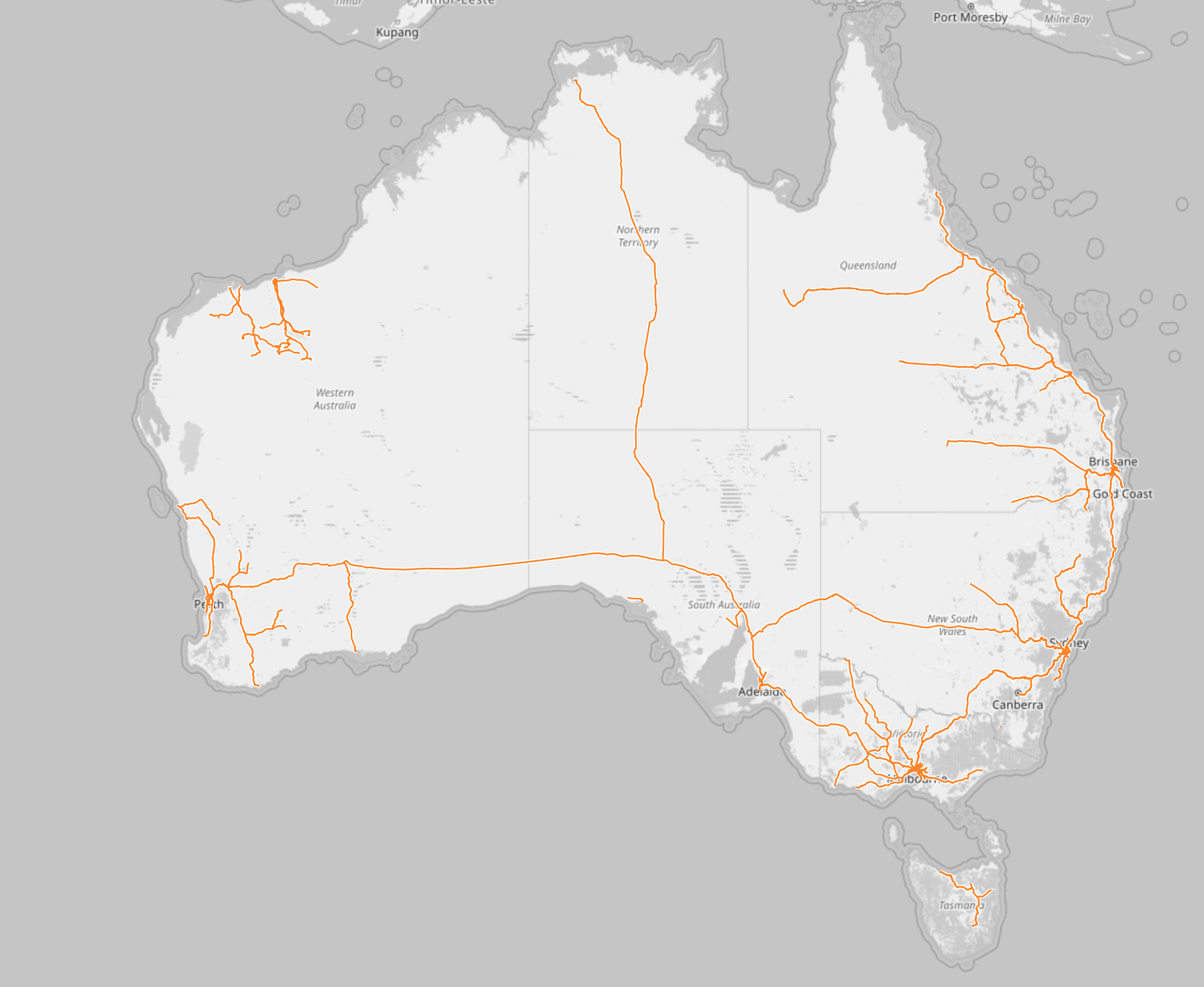
You have the lines from the coast inland, and sometimes quite a lot of them. But you can also see a line along the east coast, connecting the cities, and you can see that someone said “we need to build a railroad across the entire continent. No, two actually”. That is not to say that Australia does everything right with railroads, they have a lot of weirdness there. But you can see that the railroads had more jobs than to just move resources to ships.

(The big exception is the Pilbara region, in the north west, with its odd tangle of lines. Those are all just resource extraction lines, where the world’s heaviest freight trains haul iron ore from various mines to various ports. The mines and ports are owned by different mining companies that don’t like each other, so everybody has their own line from their own harbour to their own mine, even if a different line would have been shorter.)

So, that’s basically it. The railroad map of a country shows you a lot about how a country works, and more specifically how it worked during the late 19th and early 20th century, when most railroads were built. Where they lead to and where they don’t reflects what connections planners thought of as important, and in turn, it has shaped the way these countries developed. And personally, I always find this endlessly fascinating.

DCC Decoder v3: Buck converter

As a follow-up to my post about the DCC decoder, let me present the newest version of the decoder. It looks mostly similar, but there are important differences as well:

A photo of an electronic circuit board

The frame on the outside isn’t a change, that’s just how the circuit board is delivered. In the pictures of the old one I had just removed it. But besides that, there are actual changes, even if it looks the same and runs the exact same software.

Let’s start by going through the changes at the upper edge:

An excerpt of the last photo, with three areas marked and numbered 1, 2 and 3.

  1. The rectifier diodes are rearranged to take up less space.
  2. The transistor and resistor used to communicate back by increasing power consumption have moved.Also, the value of the resistor is now 220 Ohm, because it is now directly connected to the 15-to-25 Volt output of the rectifier, instead of the 5 Volt regulated power supply. I’m not entirely sure anymore why I did it differently before. But now it will only work this way due to how I’m generating the 5 Volt power here.
  3. As mentioned before, the Zener diode is gone and there’s just a single 22 kOhm resistor at the DCC input line.

And that brings me to the main part: The way I turn 15 to 25 Volt DC into 5 Volt DC is completely different.

Another excerpt from the photo, focusing on a small chip with six pins.

The core of the new design is a switching voltage converter called Roh BD9G102G. It’s small, essentially a six pin version of the package used for the diodes and the transistor, but it can do a lot. However, it needs a lot of external components to work correctly.

(Aside: Rohm calls this package an SSOP6, but it has the exact same dimensions as an SOT23-6, which is the “official” six pin version of the SOT23 used by the diodes and transistor. No idea why there are these two different names. Both SSOP6 and SOT23-6 are, by the way, 0.3 mm wider than the normal three-pin SOT23.)

The basic design of this power regulator is completely different than the linear regulator used in the previous design. As mentioned there, that linear regulator can be thought of as a self-adjusting resistor, that ensures that for any given current, it always sucks up exactly so much voltage that the end voltage to ground is 5 Volts DC. That’s rather inefficient; the difference voltage times the current just gets turned into heat.

In contrast to this, a switching regulator (specifically a so called buck converter) is first and foremost a switch and some logic to turn it on or off. It is always part of a circuit that also contains a diode, an inductor coil and a capacitor. It works like this:

A circuit diagram. To the left is a power supply. Connected to its plus output is a switch. Connected to that are the cathode of a diode (whose anode is connected to minus) and a coil inductor. At the other end of the inductor, a capacitor is connected, again to minus. Finally, at the end, a resistor is shown as an example load.

First the switch closes. The full 15 to 25 Volts (this regulator can deal with up to 42 Volts) is now present at the input of the coil, while the diode is blocking. A current can now flow into the coil. Thanks to its self-induction, the voltage at the end rises only very slowly. At the same time the output capacitor is loaded.

Once the voltage at the coil output exceeds the target (say here 5.05 Volt), the switch opens. Now the coil and capacitor are supplying the power that is stored in them to the load. The diode conducts now, to close the loop. During this phase, the voltage will slowly drop. Eventually the switch closes, and the whole deal starts again. How often this happens depends on the regulator in question. The one I have here has a frequency of one Megahertz.

The advantage of this design is that it will supply more continous current on the output of the coil than goes into the switch on average. The concept does not rely on any power getting turned into heat. Of course some losses are inevitable, but this regulator can, under the right conditions, still reach efficiencies of more than 90%. In my use case, I’ve seen the whole decoder and LED use about half as much current as before.

To do all this, a lot of parts and pieces are needed. Here’s all of them:

A larger extract from the last photo. It shows the same chip with six pins, but now more surroundings. Different components are highlighted and labelled numbers 1 through 7.

The converter is number 1 here, and the core of the design. The important pins are input (bottom center), switch output (bottom right), Ground or minus (top center), and feedback for measuring the voltage at the end of the coil (top left). Top right is “boost”, whatever that is, and bottom left is “enable”, which I could use to turn the converter off, e.g. if I had a design where it supplies something that I don’t need all the time.

The two capacitors at the input (number 2) ensure that there’s always enough current available to flow through the switch, and to supply the internal logic of the regulator. According to the datasheet, one would have been sufficient, but since DCC power can sometimes cut out, I decided to take two.

Next to it is the diode (number 3), which closes the loop when the switch is open. Next to that is the coil (number 4), the one part with the labelling that is the most easy to read in normal light, even though it’s black on gray. I’ve been using a lot of extra lights for this photo.

Even so, the labelling is misleading: The last digit isn’t part of the number, it’s the exponent, or the number of zeroes you need to add to the number. 220 does not mean 220 µH, it means 22. That it means µH and inductivity at all is something you just have to learn by heart, it doesn’t say so anywhere. Other labelled components use the same logic, for example the resistors: 123 means 12 kiloohms (not that you can actually read that without a magnifying glass), and 2200 means 220 Ohm. The capacitors, on the other hand, are not labelled at all, which feels almost refreshingly honest.

Below the coil are the output capacitors (number 5), which stabilize the power, especially if the coil is empty. Once again I probably overdid it; one should be sufficient, but this way I know I’ll never have too little capacitance.

Directly next to the regulator is the boost capacitor (number 6). I don’t know what it does. The datasheet says “Add a 100 nF boost capacitor there”, so I did. It’s connected between the switch output and a dedicated “boost” input.

Above and to the right are two resistors, which form a voltage divider. This chip is an adjustable version, which can output a wide variety of voltages. You need to build such a voltage divider to ensure that the feedback pin of the regulator gets exactly 0.75 Volts when the output voltage matches your target. You could also make this field adjustable by using a potentiometer here.

Adjustable sounds better, but honestly, for me, it’s just annoying. Non-adjustable regulators (no matter what type) are really just adjustable regulators with these resistors already built in. Sadly, this type is not available in a fixed version. (For bonus points: Any “fixed” regulator can be adjusted by adding such a voltage divider anyway, if you really want to, for some reason.)

I would have actually preferred using a regulator that doesn’t require additional resistors here, and maybe even already includes the diode. Those exist, for example the Texas Instruments LMR50410 series, but they have a problem: I can’t get them. If I order now, the earliest I’ll get one is the middle of march. That’s the case for a lot of components right now, in particular the newer fun ones. The main advantage of the Rohm BD9G102G isn’t what it does, there are quite a few similar components; it’s that I can actually get it. Or at least I could two weeks ago; right now no dealer seems to have them in stock (though at least it would only take until october to get more), so it’s a good thing I ordered enough of them. The chip crisis is very real.

This is ultimately all there is to it with this converter. Just for fun, here’s the overall circuit diagram:

A circuit diagram with all the parts explained above.

An important with all of these regulators is that they are much more delicate parts and much more delicate circuits than linear regulators. The data sheet for any switching regulator will always come with fairly precise advice for how to design your circuit board. You don’t want any part of it to become an antenna and generate electrical interference with its high frequencies. Otherwise this could disturb your circuit or others around you (e.g. distort radio signals). All the copper wires on the board and the capacitors can also start oscillating if you’re unlucky, and generate weird voltage spikes. That means proper circuit board layout and using the correct capacitors, diodes and so on is really crucial. My exaggerated input and output capacitors are things that I wasn’t actually certain would work. At the end of the day, if you just follow the advice in the data sheet, it should work well, and it did so here. Still, I’m very relieved that it worked on first try.

Model railroad signal decoder

In the past few weeks I’ve built a model railroad signal for garden railways with a custom DCC decdoder. Here’s what it looks like:

I’ve heard from a number of people that they thought this was interesting, but they didn’t really understand what I was doing. So today I’ll try to explain the core of it all, this circuit board:

A complex electronic circuit board.

And here’s the associated circuit diagram:

A complex electronic circuit diagram.

I’ll try to explain why this is the way it is and what it does.

(This whole explanation is aimed at people who have never done anything with electronics before. If that’s not you, then this may be a bit boring. Also, I didn’t come up with any of the parts of this. Most of this is based on things I learned by reading OpenDCC and Mikrocontroller.net. I’m sure I still made a lot of mistakes, though, and they’re definitely all mine and not the fault of anyone on these sites.)

The goal

First let’s talk about requirements. My goal was to build an american signal type “Searchlight”. Such a signal has between one and three lamps. Thanks to a clever electromechanic design that moves different color filters around, each lamp can show different colors - up to three from a total selection of four.

Replicating this system for a model railroad is not practical. I need something else. Having multiple colored LEDs next to each other wouldn’t work; they’re too big and I want it to all look like one light source. There are LEDs that contain red, blue and green in one housing, but that would require a lot of wires quickly that all have to be put in the mast. The solution is this:

Two wired LEDs with four pins sticking out of each.

This is an “adressable” LED, better known under the name “Neopixel” used by a large american online store. There are many variations from different manufacturers. The key thing is that each LED has a tiny control circuit built right in. It takes four wires: Plus five volts, minus, data in and data out. If you have more than one, you can connect the data out of the first directly to the data in of the second and so on. Connect the plus and minus as well, and you can control almost unlimited amounts of LEDs with just three wires.

The data line has a special protocol that you need to generate. Basically you need to switch it from 0 to 5 to 0 volts again and again at a certain rate; the time it stays at 5 volts (“high”) determines whether you’re sending a 0 or a 1. From these bits you form bytes, which tell each LED what specific color value to send.

Due to this dataformat, you definitely need some electronic circuit controlling the signal, and the first requirements for this are:

  • Provide five volts DC power
  • Generate the data for the LEDs in the correct format

The Input

There are a lot of options for designing the input side of things. In my case, I’m assuming the signal is electrically connected to the rails of a model railroad that is controlled digitally. With digital command control (DCC), the voltage at the rails has a constant value of about 15 to 25 volts, larger for larger scales. This voltage constantly flips polarity; first plus is on the left rail, then it goes to the right rail (and minus vice versa), and then back. It’s like AC in normal wall outlets, but with very abrupt changes instead of a smooth sine wave.

An irregular square wave shown on an oscilloscope.

This voltage has two tasks. First it supplies the locomotives with power, but it also transmits information. If one of these change-and-back sequences is long, it transmits a “0”; if it’s short, it transmits a “1”. These bits together then form the bytes that form the messages that say things like, “Locomotive three run at speed step 64” or “switch 10 switch to direction left”.

This decoder uses both features. The digital voltage provides both the data and the power. For a locomotive, that is required since the only conductors you have are the rails. This is a stationary decoder, so I could have designed it so that it only uses digital commands, and gets the power from an external power supply. However, I wanted to use the least amount of cables, so I’m using the simple version.

With that, the requirements are fixed. The circuit has to:

  • Turn the digital power (15-25 Volts, AC-ish) into 5 Volts DC
  • Read and understand the digital data signal (decode it, hence the name “decoder”) and calculate the colors for the LEDs.

Computation

This calculation is the real key here. The digital signal has a completely different fromat than what the LEDs expect. It’s slower, but also has completely different meaning. At best it transmits “set switch or signal 10 to state 0”. Which color values are associated with that, let alone any blending to make it look nice, are things the signal has to decide for itself. There is no way to build a simple stupid adapter here; I need a complete computer.

Luckily, you can get those for cheap and in really tiny.

A single small computer chip.

The ATtiny85 costs about 1€ depending on how many you order, and it’s smaller than one cent coin (I think in basically any currency), but from a technical point of view, it is essentially a full computer. It has all the important parts anyway. There is a CPU that can run at (depending on the version) up to 20 MHz; half a kilobyte of RAM and eight kilobyte of internal storage for the program. Multiple programs is a bit of a challenge. If you know Arduinos, the ATtiny85 is related to the ATmega328p in the Arduino Uno and Nano. Far less powerful, but cheaper and significantly smaller.

What it lacks are all the surroundings like keyboard and screen for input and output. The chip is designed for applications where this isn’t needed, or at least only minimal things. The software that you write can assign each pin (okay, five out of eight) freely for different tasks: The pin can work as an input, telling the software whether there’s a low or high level of voltage at it (meaning 0 or 5 Volts), or it can work as an output and write high or low values, meaning setting the pin explicitly to 0 or 5 Volts.

There are other options for the Pins as well; among other things it can also read analog voltages and generate them to some extent. But for this task I only need the simple digital high-low inputs and outputs.

These types of chips, known as microcontrollers, exist in thousands of variations by different manufacturers with very different performance characteristics. They are the key part of basically everything that’s digitally controlled these days. Washing machines, everything that plugs into a computer including every single Apple lightning cable, TVs, TV remotes, amazing amounts of parts in cars and so on are all the realm of microcontrollers. The ATtiny85 is, as the name implies, very much at the low end of the scale (though there are smaller ones), and even here, it is a bit out of date. But it is very easy to program and very forgiving of mistakes, which makes it great in hobby situations.

To run, this chip needs around 3-5 Volts DC (some versions like the one here can also run on a bit less) and exactly one capacitor. I’m already generating 5 Volts DC for the LEDs anyway, so this chip will get them as well. That means for all the calculation, only two pieces of hardware are required.

Excerpt from the circuit diagram. Shows a microcontroller and a capacitor.

Excerpt from the photograph of the circuit board. The microcontroller and its capacitor are highlighted.

There is some more associated hardware, though, for getting the program (which I’ve written myself) on the chip. For that you need a programmer, a device that you can buy for some money, or make yourself astonishingly easily from an Arduino. It needs to be connected with six wires to the chip. The standard for this is with a six-pin plug, which I’ve thus included here as well. There are standard six-wire cables for this.

Excerpt from the photograph of the circuit board. The six pin plug is highlighted.

You could connect the cables differently, for example with some sort of spring-loaded contacts on some programming circuit board you’d have to build for that, or in the worst case, just temporarily solder the cables in there. But the plug version is both simple and convenient, with the only downside that it makes the circuit a bit more pointy.

5 Volt DC

The 5V DC is a fairly boring topic compared to the slightly complex software. But on the other hand, a lot of the circuit board is just concerned with it, and it is really the basis of the decoder. It fundamentally consists of two parts:

DC

To generate DC I’m using a bridge rectifier, a simple standard setup of four diodes.

Excerpt from the circuit diagram. Shows a bridge rectifier.

The diodes are arranged such that no matter what, the rail that is currently “plus” is connected with the internal “plus”, and the rail that is currently “minus” is connected to the internal “minus” (also known as ground, shortened to GND).

To simplify the circuit board I’m using double diodes. These are parts that contain two diodes in one housing. The diodes are connected with each other and the three pins.

Excerpt from the photograph of the circuit board. Two identical parts with three pins each are highlighted.

The first (here lowest) pin is connected to the cathode of the first diode. The middle pin is connected to the anode of the first diode and the cathode of the second. The top pin is connected to the anode of the first pin. That means I need only two parts to have four diodes. There are integrated bridge rectifiers you can buy, but those are optimized for normal AC and not ideal here.

5 Volt

From the rectifier we get between 15 and 25 volts DC, depending on what the model railroad is set to. Honestly, 25 is probably excessive, but I preferred to err on the side of safety. Either way, even the low end of the scale will immediately fry the small LEDs and the microcontroller. That means I need a voltage regulator.

Excerpt from the circuit diagram. Shows a voltage regulator with a lot of capacitors, and a diode connecting the output to the input.

Excerpt from the photograph of the circuit board. A large piece with three pins on one side and a metal tab on the other is highlighted together with some capacitors.

The voltage regulator, here an UA78M05, is a fairly complex integrated circuit that contains a big output transistor that conducts current. Part of the circuit checks whether the output voltage matches the expected 5 Volts; it opens or closes the transistor more or less to ensure it does. For stable working it needs a few more capacitors at both input and ouptut side.

An oddity in the design I’ve chosen is the diode.

Excerpt from the last picture. Only a single part with two pins is highlighted.

During normal operations it is blocking, meaning it does nothing. You could totally get rid of it. The problem is when I program the microcontroller. In that case the 5V for the whole design comes from the programmer device. In that case the voltage regulator has 0 Volts on the input side and 5 Volts on the right. It does not like that and could be destroyed from that, since current is going the wrong way round in there. In this case the diode conducts the 5V (minus 0.7) to the left side. That is not enough for the regulator to do anything, but it is enough to ensure that it doesn’t break.

The specific diode, type 1N4148, is one I picked because I had some of those laying around.

The whole voltage regulator is a very simple solution, but not a great one. The very high-level view is that it works like a self-regulating resistor. That means the current going through it is the same on the input and output side, and only the voltage changes. If you get 5 Volts with 20 milliampere out, then you need to put 20 milliampere at, say, 15 Volt in. The difference of 10 Volts times 0.02 Ampere means you loose 0.2 Watts, which get turned into heat. That may not sound like much, but it already gets warmer than I expected. I think with up to three LEDs it should be alright, but there’s definitely room for improvement.

The preferred solution would be a so-called buck converter, a significantly more complex part that needs more additional components. I’m going to try that out for the next version of this decoder.

Data Input

To parse the DCC signal, it’s sufficient to read the data from a single rail. If the rail is the “plus” rail, it has a high voltage (compared to the internal Minus or 0 Volt level); if it is the minus rail, then it is connected via the rectifier to the internal 0 Volt level. Using just one input means I can’t tell the difference between “track is minus” and “there’s no power from the track”, but since the decoder is always wired in, I don’t think that’s important.

The problem is that when the track is positive, it has a voltage of 15 Volt compared to ground. That is way too much for the microcontroller. To solve this I’m using a small design with a Z-diode.

Excerpt from the circuit diagram. Shows a resistor in series with a zener diode. Another wire branches off from the connection between the resistor and the zener diode.

The special thing of a Zener diode is that if you put it in reverse, where normal diodes block, it will start conducting anyway if the voltage exceeds a certain level (and stop once it doesn’t anymore).Here I’m using a 4.7 Volt one. If the input has 4.7 volts or more, it starts letting so much current through that the voltage drop over it is pretty much exactly 4.7 Volts, which is enough to be read as “High” by the microcontroller.

The amount of current that the Zener diode lets through can quickly grow very high, which in turn can destroy the diode. That’s why it needs to have a fairly large resistor in the line leading up to it, to ensure that there is never a lot of current going through it. The microcontroller itself doesn’t need any current from this pin, it just measures whether the voltage is above or below a certain threshold. That way it can read the DCC signal.

Excerpt from the photograph of the circuit board. A small piece with three pins highlighted together with a resistor.

A weird specialty here: Like all diodes, a Zener diode has only two ends that need to be connected. For some reason, the one I have here comes in a package that has three leads. (Yes, that is the same package as for the rectifier diodes.) The third lead isn’t connected to anything in the diode, and it isn’t connected to anything on the circuit board either. It’s just soldered in to hold the Zener diode safely in place. I’m not sure why it was designed this way, but at least it makes it impossible to solder it in the wrong way round.

Bonus: The decoder also works flawlessly if I just leave out the Zener diode and use only the resister. I’ve tested this. The excessive voltage gets transferred away via built-in protection dioes on the microcontroller which connect it to the 5V rail… somehow. I haven’t honestly really understood what’s happening in that case, and in particular how I calculate it. I know from the internet that somewhere between 22 and 33 kiloohms works well here, but I can’t actually show you the maths that prove why. That’s why I preferred to use the version with the Zener-Diode here, which is much more easily understandable. The next version of the decoder, which will get more components elswhere, will probably not have the Zener-diode though, just to save space.

Output

The output hardware for the microcontroller is simple because there is none. One pin of the controller is directly connected to the data in pin of the first LED.

There are Best-Practices documents for these LEDs that recommend adding a resistor, ideally close to the LED. Since I don’t have long leads to the LED and only use relatively few, I haven’t needed that this far. If I do, I’d probably add the resistor to the LED instead of the decoder.

That means the decoder is done. Well, almost.

Output part 2: Acknowledgement

A problem with classic digital model railroads is that the protocol is strictly one-directional. There is no way for the decoder to send any information back. No part of the circuit I’ve designed here can provide any voltage back to the tracks or similar.

Most of the time that’s no problem. But if a digitalsystem wants to configure the settings that the decoder has, for example setting the address it responds to, then it would be nice if there was a way to read the existing value, and get a signal that a new value has been written successfully. For that, there is a small hack: The decoder in a locomotive simply briefly turns on the locomotive’s motor. This increases the current drawn, and that can be measured.

The problem for my decoder is that there is no motor connected. So I need to increase the power draw some other way. In the first version I did that by simply turning the LEDs on fully white, which actually works. But there are scenarios where this might not be sufficient, for example if I build signals for N gauge with smaller LEDs that draw less power.

So that means I need to increase power by letting current flow through a resistor. The resistor needs a larger housing because it needs to withstand more power that gets dissipated in it. I guess one in a smaller housing would work just as well, since the power is applied only very briefly (six milliseconds), so it doesn’t really have the time to get hot, but better to err on the side of caution.

Excerpt from the circuit diagram. Shows a resistor in As a load for a MOSFET.

Excerpt from the photograph of the circuit board. A different small piece with three pins highlighted together with a different resistor.

If you look closely you may see that the circuit diagram and the board both say 47 Ohm, but the resistor is actually 68 Ohm. I did the maths again and changed my opinion after I had alreaady ordered the circuit board here.

The resistor cannot be connected directly to the pin of the microcontroller, because the microcontroller can’t deal with all the current that would flow through it. Instead I’m using a small transistor, specifically a MOSFET of type 2N7002. This thing is nice and easy: If the microcontroller output pin is at 5 Volt, then it is open, if it’s at 0 Volt, then the transistor is closed. There is no additional hardware required.

The only real problem with this transistor is that it is the third different component in the same exact package. It is the same package, known as SOT-23, that is used by the Zener diode and the double diodes for the rectifier.

Excerpt from the photograph of the circuit board. Highlighted are four different components that all look alike and all have three pins each.

If you shine a lot of light on it, then you can maybe see that each of them has some markings. These markings are difficult to read under the best of circumstances, and they’re only a code for the component; you still have to look up which thing it actually is in a table somewhere. Really, what you should do is keep these pieces in the labelled plastic bags they came in until you need them, and then immediately put them back before you open the next bag.

(I deliberately ignored something here: There is a fairly complex extension of the DCC standard known as Railcom which decoders can use to answer. This requires additional hardware on the decoder, which I didn’t add, and also a more powerful microcontroller.)

Conclusion

The photograph of the circuit board again. All parts are highlighted in different colors.

That’s all there really is to this decoder. I’ve designed the circuit diagram and the board layout with Eagle. I wouldn’t say I really like the program, but it can do everything you need, and it’s free for hobby purposes. I did not make the circuit boards myself, but instead had them made at Aisler. They charge a little over six euros for three of these boards (size about 2 by 2.5 cm). I’ve soldered it together myself, and indeed, it happens to work.

Alfa Romeo Giulietta Racing in 2018

With the first few races including Alfa Romeo Giuliettas already completed, it is about time to update [the old post](https://ferroequinologist.de/blog/2017/10/Alfa+Romeo+Giulietta+im+Motorsport) for things going on in 2018. There’s actually a lot!

TCR

A quick recap: TCR is a specification for C-segment touring car racers that are comparatively cheap but quick and look dramatic. Many different series use them. The TCR version of the Alfa Romeo Giulietta is built by independent tuner Romeo Ferraris (no relation) and raced in various series, either by Romeo Ferraris themselves, some front company, or their customers. And there are more of them every year!

The big news is that the headlining TCR World series is changing. Previously the WTCC (world touring car championship), officially the higher-ranking series, was in a slow but steady decline because nobody was making the TC1 cars used there. For this season, the series has adopted the TCR regulations, and also the staff who used to manage the old TCR World series. The TCR World series is officially cancelled, and the WTCC is renamed to [WTCR](https://www.fiawtcr.com), officially expanded to World Touring Car Cup. Apparently it’s no longer allowed to be a championship because the TCR regulations do not allow full works teams.

The Giulietta will be there again. [This time it will run under the team name “Mulsanne Racing”](https://www.fiawtcr.com/team-mulsanne-counts-on-experience-in-wtcr/), which was also already used for the TCR Middle East 2017 (the Giulietta did not participate in the TCR Middle East 2018). You can actually see that they changed the front bumper a little bit compared to the 2018 car, presumably to improve airflow into the central cooler. I still have the impression that Mulsanne Racing is not really an independent entity, but just some shell that Romeo Ferraris use, since they have absolutely no internet presence. The closest thing I could find is a “Mulsanne Racing” in Dallas, Texas, a company that offers fractional ownership in go carts and which is presumably no relation. But I could be wrong here.

The drivers this year will be italian veterans: Fabrizio Giovanardi, who was champion in various touring car series, and Gabriele Tarquini, who has a history in Formula 1 and was very successful in various touring car championships. Both of them have driven Alfas before. Overall, this is the main Alfa Giulietta effort in the TCR.

But the customers are also still around! First, the simple story: In Italy, V-Action, who ran two Giuliettas last year, [will continue to do so](http://www.acisport.it/it/CIT/notizie/2018/29710/v-action-racing-team,-ecco-la-prima-alfa-romeo-giulietta-tcr-by-romeo-ferraris.). This time they will hopefully be able to run them the entire season instead of only from race five.

[The very first race with a Giulietta this year](http://world-challenge.com/race/2018-03-cota/) took place in Austin, Texas of all places. This race was part of the [Pirelli World Challenge](http://world-challenge.com), despite the name a US-only race series with many categories (that usually run independently) that added a TCR division this year. Romeo Ferraris together with one Tim Munday of BAM! Motorsports actually set up a whole [import and support business for the Giulietta](https://www.alfatcr.com), to sell it to teams racing there. This makes it the first time that the Giulietta is sold in the US at all. So far they seem to be running just one car, on their own, but it did at least get a fourth place in the first round (but did not finish in the second). The homepage also lists events from the “IMSA Continental Tire SportsCar Challenge”, another sports-car racing series whose name also starts with a tire manufacturer and ends with Challenge. The difference, apart from the tire manufacturer, appears to be that this one is an endurance race series. That series also added a TCR division for this year, but at least for the first race this year, there was no Giulietta there.

Then we got the UK, which went from no Giuliettas racing in 2017 to three in two different series. This country got its own TCR series this year, creatively titled [TCR UK](http://www.tcruk.co.uk). The intention is that this will be the junior series to the more higher-spec BTCC (see below), but some drivers will compete in both. The Giulietta is run by [Laser Tools Racing](https://www.lasertoolsracing.co.uk), featuring Aiden Moffat and Derek Palmer. In the first round, the first race had a place 2 for Aiden while Derek did not finish. In the second round, Aiden did not finish (ran out of fuel in the penultimate lap while on second place) and Derek Palmer, who was battling technical issues the entire weekend, finished last. So far a mixed but not entirely hopeless start.

There’s no word on TCR Giuliettas elsewhere, but the thing with TCR is that it could always appear as a guest star somewhere. The TCR Europe, this time a full series, looks like it might be a nice spot. I don’t have high hopes for the TCR Germany as a regular, but I wouldn’t be surprised to see it as a guest starter once more. And there’s still that one Giulietta owned by Hungarian team Unicorse that doesn’t seem to be doing anything.

(By the way: English-language Wikipedia currently claims that Unicorse raced the Giulietta in the ETCC in 2016 and 2017. That is incorrect. They didn’t get the car until 2017 and it does not show up in any result lists for the ETCC 2017. Unicorse would have liked to run it there, according to some press releases, but that hasn’t happened yet. The ETCC is now dead, but TCR Europe is still around.)

Note that while TCR regulations are also used for endurance series, I have not heard of anyone who wants to run the TCR Giulietta in an endurance series, and Romeo Ferraris don’t seem to be marketing it there either.

BTCC

The [British Touring Car Championship](http://www.btcc.net) is the “main” touring car series in Britain, featuring cars that are basically silhouette racers: While the body shell is from the factory (and then heavily modified of course), much of suspension, brakes and drivetrain, including optionally the engine, are standard parts. As already announced in 2017, they now feature their own Giulietta as well. Built by Handy Motorsport and driven by Rob Austin, the car is now finished and [has done first tests](https://www.autosport.com/btcc/news/135068/austin-puts-new-alfa-on-top-in-btcc-test). The team has said that they are very excited about its potential. Apparently the great thing about the Giulietta, in this series that removes almost all technical aspects that make the car unique, is the wheelbase and the short overhang.

Will we ever see the BTCC and TCR Giuliettas head to head to see which is the fastest Giulietta in all of Britain? It seems unlikely, but maybe we can compare lap times once they’ve run on the same courses. An initial look shows that TCR and BTCC are roughly in the same ballpark, at least on Silverstone (based on the one race the TCR UK had so far in 2018 and the BTCC race in 2017), with maybe a slight edge for BTCC.

(Note that Aiden Moffat, from the TCR UK, is running with Laser Tools Racing in the BTCC as well, but here with a Mercedes Benz A-Class. Traitor.)

SA Endurance Series

Can you believe I missed a racing Giulietta the last time around? Even though I found no less than six major efforts? Well, I did, and I want to apologise. The one I missed (and found out about) runs in the [Mopar South African Endurance Series](https://www.saenduranceseries.co.za), and the [Giulietta is run by Arnold Chatz Cars Racing](https://citizen.co.za/motoring/motoring-motorsport-motoring/1832019/alfa-romeo-giulietta-heads-to-phakisa-raceway/). I haven’t been able to find any technical details about this one, but it looks like one of the more modified ones. Lower ride height, big front and rear wing, but it does not have the fender extensions that make the TCR and BTCC Giuliettas almost square (as if the existing Giulietta wasn’t annoying enough to park in old parking garages already). Once more, it is fascinating how many different ways people find to reinterpret the Giulietta’s front bumper to make it look race-worthy… and I like almost all of them (with the obvious exception of the [Mosca/Etruria TCT one](https://it.motorsport.com/tcr-italia/photo/main-gallery/andrea-mosca-alfa-romeo-giulietta-qv-tct-10615536/)) more than the stock version.

The car got an overall fourth place last season in its class and hopes to get even better this year. In the first race, it easily won its category (as one of three) and managed to beat the odd GT4 car, going for seventh place overall. That does not sound all bad.

BRSCC Alfa Romeo Challenge - Giulietta 8C

On the less serious but amazingly still british end of things, we get the [BRSCC Alfa Romeo Challenge](http://alfaracer.com), a series exclusively for Alfa Romeos, primarily aimed at hobby drivers. It’s far from the only of its kind, and you will generally not find the Giulietta here because they’re still too new. The standard cars here are 156, 147 (both without facelift), and the odd 155 and even 75. Also some Fiat Puntos, which offends me on a personal level.

But they do allow odd cars in an “invitation” category, and being the home of Doctor Who, Top Gear, The Slow Mo Guys and James Bond, you can bet someone has come up with something odd. One Roger Evans is [building a Giulietta with the drivetrain from a fire-damaged 8C Competizione he found on Ebay](https://www.pressreader.com/uk/motor-sport-news/20160720/281874412759399). Apparently the wheelbase is almost the same, so it’s at least in the generally possible category, but it’s still a project that has been going on for years now. The [2018 season preview](http://alfaracer.com/2018-season-preview/) on the series home page expresses hope that maybe it’ll run this year. Is that realistic? Your guess is as good as mine, but there’s no way I’m skipping a story like that.

Historic note: FIA Alternative Energies Cup

I’m just going to do this quickly because the official website is a nightmare, all the information I can find is italian, and frankly, I just don’t care that much. The FIA Alternative Energies Cup is a rally series for cars with alternative energy, meaning anything but gasoline or diesel. Team “Montecarlo Engineering Racing Team” [has run a Giulietta converted](http://www.automotornews.it/automobilismo/montecarlo-engineering-racing-team-sceglie-motor-village-arese-per-celebrare-un-anno-di-successi-con-le-energie-alternative/) [to LPG equipment there](http://www.automotornews.it/automobilismo/sua-altezza-serenissima-principe-albert-ll-di-monaco-e-l-alfa-romeo-giulietta-a-gpl/), as well [as a 1990s era GTV](http://blog.vendiauto.com/il-montecarlo-racing-team-alla-conquista-del-mondiale-fia-alternative-energies-cup-2015-con-unalfa-romeo-2015). Apparently they had some success in the “other” category. From what I can tell, it seems like the car is stock except for the LPG conversion and the paint scheme. But it has sponsor stickers, a number on the door and it appears in official result lists (I think), so it deserves to be on this list. From what I can tell on Wikipedia, the same series has also seen a number of wins by at least one LPG converted Mito.

Bonus!

[Mitjet](http://www.mitjet2l.com) is a specification for small, low-weight, simple race cars for beginners, with standard technology, standard motor, but slightly different bodies that can, with stickers, be made to vaguely look like a Mercedes, Audi or BMW. In the [italian Mitjet series](http://www.mqcorse.it), someone put stickers on their car that made it look [vaguely like the current Giulia](https://it.motorsport.com/all/photo/main-gallery/giacomo-riva-15120206/?a=1009992). It’s obviously not licensed, there are no logos and the four-leaf clover is on close inspection some other shape, but still, this is the closest that car has come to actual racing as far as I can tell. Still more than the Stelvio.

In news that is almost as exciting, long-time bottom-tier Formula 1 team Sauber is getting Ferrari motors this season, but thanks to a sponsorship deal, [they’re putting Alfa Romeo stickers on the car](https://www.sauberf1team.com/race-cars/coming-soon-alfa-romeo-sauber-f1-challenger) and pretending Alfa Romeo has something to do with this. In the first race they had [absolutely no success](https://www.formula1.com/en/results.html/2018/races/979/australia/race-result.html) with this.

Speaking of TCR and italian touring cars, remember Tecnodom? They unsuccessfully ran a Giulietta in the TCS spec a while back, and with slightly more success two Mitos in the same class. Apparently they now also want in to the TCR business, specifically TCR Italy, and they want to run with an Italian car they built themselves. But since the Giulietta is taken (TCR regulations allow only one manufacturer for each TCR-spec car), they are [using the new Fiat Tipo](https://www.touringcartimes.com/2018/03/22/kevin-giacon-tests-fiat-tipo-tcr-preparation-2018-season/). I am obviously rooting for the Giulietta over the Tipo, but I guess I am rooting for the Tipo over all non-italian cars.

This weekend

This weekend (April 7th/8th) will actually feature a number of series that I’ll be looking at:

  • The first race of the BTCC
  • The first race of the WTCR
  • Less interesting but I’ll still look at the results, the second race of the Formula 1.

Alfa Romeo Giulietta in Racing

This is a best effort at a list of all the ongoing, finished or upcoming projects where the Alfa Romeo Giulietta (type 940, the current one) is used as a race car.

Why am I doing that? Well, mostly because I drive that car myself (not in racing) and I was curious. But also because I can already see that history won’t be kind to this car, and will probably be cited as one of the low points in this storied italian brand. This has nothing to do with the car itself: It’s fun to drive, practical, has great styling and good marks on stuff like reliability and safety. The problem is that in 2011, the Alfa 159 got cancelled so Fiat could build more of their Panda. This made the Giulietta, a fancy-looking but ultimately harmless VW Golf rival that never sold all that well, the flagship model of one of the greatest brands in automotive history. And that was just sad.

And then Alfa Romeo is one of the great motorsport brands, winning for example the first ever Formula one championship. Alfa Romeo is literally where Enzo Ferrari got his start, and they built legendary race cars ever since. Until about 2004, when the 147 Cup ended, and there has been no works-supported racing by them ever since. Now we get rumors that Alfa might join the DTM (Alfa clearly doesn’t want to), or that Alfa might join the Formula 1 again… by relabelling last year’s Ferrari engines that some smaller teams buy. That sounds reeeeeally exciting. But the thing is: If you want Alfa Romeo racing, you can already get it, and it’s great fun to watch. And they’re racing the Giulietta! In at least seven different projects! Here’s the ones I found:

TCR

TCR is a fairly new race car specification designed to be cheap but fun, with cars that look really dramatic but are accessible to a wide variety of teams. These cars are used in a number of different championships, some for one or a few countries and a flagship [TCR International](http://tcr-series.com) series. It is also used for a growing number of endurance race series.

The car specifications are based directly on the SEAT Leon Cup, and the cars are in practice mostly designed by independent tuners with sometimes more and sometimes less support from the manufacturer. Big wings and engines tuned to go up to 350 HP are also part of the concept. Currently eleven manufacturers have cars there, with more on the way. The Giulietta is one of them, with the race version [designed by tuner Romeo Ferraris](https://www.romeoferraris.com/automobili/giulietta-tcr/) (despite the name no direct relation to either manufacturer). Alfa Romeo’s support seems to have started and ended at them saying „good luck, guys!“, while e.g. Volkswagen designs the complete car and sells it to others. Despite that, it’s proven capable of winning races.

Its first use was in the 2016 TCR International championship, with the Romeo Ferraris team, where it proved underpowered and in need of major work. It skipped a few races, then ended in a new but still not that competitive version. Over the winter, a lot more work happened, and it appeared again in the [TCR Middle East](http://middleeast.tcr-series.com), a very small series that was mostly european teams testing their new cars and drivers. Here it proved competitive, getting a number of second places. Now it’s again in the international series, and it managed to win the [very first race of the season](https://www.youtube.com/watch?v=hK7qZKcrvv8&t=13s) outright. Since then there have been more victories and podium positions. Performance has not been quite consistent enough to be a serious championship contender, but it’s getting there.

A note on team names: In 2016 it was „Romeo Ferraris“, then in the middle-east series it was „Mulsanne Racing“, and now it’s „GE-Force racing“. As far as I can tell most operation is handled by Romeo Ferraris either way, with key personnel such as Michele Cerruti (driver, team manager and one of the people who developed this car) appearing in all these places. However, Romeo Ferraris will also sell this car and so far managed two sales to other teams.

The first is Hungarian team Unicorse, [who got one car, in red](http://www.tcr-series.com/index.php/news/item/unicorse-to-run-a-giulietta-tcr-at-the-hungaroring). It has participated in the Hungarian round of the international series in 2017 (no interesting placement). There were announcements that it would appear in the ETCC, an earlier touring-car championship that also allows TCR cars, but so far that does not appear to have happened.

Two more Giuliettas are run by V-Action in the TCR Italy championship, starting in the second half of 2017. One of those was also entered for the final round of the TCR Germany 2017 as a guest starter. Keep the TCR Italy in mind, we’ll keep coming back to that.

In short, as of right now, I’d say TCR has the queen of the Giuliettas, and if you’re interested enough to have read through here then you might enjoy [following it](http://tcr-series.com). You can [watch it all for free on Youtube](https://www.youtube.com/channel/UCoSlmLSprEnTz7HjmMb7HBw).

TCT

Here it starts getting complicated. TCR Italy also allows a second type of car called TCT, which uses the same technical specifications as TCR, but only has a national instead of international type approval. I think this means that these are cheaper. In this context, TCT does not stand for twin clutch transmission, a feature you can get for normal road-going Giuliettas, which makes googling the whole thing a bit annoying.

A team called Etruria has developed a version of the Giulietta for this and [raced two of them](http://www.acisport.it/it/CIT/notizie/2017/18062/andrea-bacci,-le-nostre-alfa-romeo-giulietta-tct-pronte-al-rientro-tricolore-dopo-aver-affascinato-gli-appassionati-di-tutto-il-mondo). The overall technical data seems very similar to what Romeo Ferraris did for TCR (the specification is the same, after all), but the resulting car [looks quite different](https://ch-it.motorsport.com/all/photo/main-gallery/andrea-bacci-alfa-romeo-giulietta-qv-tct-11162181/?a=855375), with different body kit and air inlets. Personally, I don’t like it.

These cars ran in 2016 and some races in 2017 and were never all that competitive with the TCR cars. These cars have not raced at the same events as the TCR Giuliettas of V-Action, so sadly we don’t know which team did a better job. I’m not sure they will either, since at least one of the TCT Giulietta drivers switched to the TCR Giulietta.

Apart from that, TCT also featured the [car driven by Gianni Giudici](https://it.motorsport.com/tcr-italia/photo/main-gallery/gianni-giudici-sc-giudici-alfa-romeo-giulietta-tct-11162206/), a guy who will appear a lot on this list. If you look at the picture you’ll see that this car does not look like a TCR or TCT car at all, really. I don’t know what’s up with that, but if I had to guess, I’d say this: Giudici also ran a Giulietta in the VLN before that (we’ll get to that in a bit). What if he simply re-used that car here? Since it was built for a different series, it might not fit into the lower-spec TCS category (see below), so it ends up in TCT by default. The new rear wing is actually required for TCR; I’m not sure if it’s also required for TCT or Giudici simply decided it was a good idea. Either way the car didn’t prove very competitive with the cars of any category, and it hasn’t been seen since.

TCS

TCS is yet another specification for race cars found only in Italy. In 2017, the TCS is run as a separate (and mostly Seat-only) series, while in 2016 TCS cars took part in the TCR championship, classified separately. Before that, the story gets even more complicated; at one point, the TCS was actually the only type of car in the Italian Touring Car Championship.

The fundamentals of the car remain fairly similar, though: Relatively little changes; Cars get cars fitted with roll cage, safety equipment and some tuning to engine and suspension, but no massive wings or much bigger wheels or similar. There are further sub-divisions based on displacement, but the starter field tends to be small, so e.g. TCS 1.4 has generally only had one or maybe two entries these season.

This series has featured several Giuliettas. Sadly the sources for this are all in Italian, and they’re full of people announcing things that then never happen, so this part took a bit of digging and I don’t guarantee that my information is correct. That said:

This year there are no Giuliettas that actually ran. [Leone Motorsport](https://www.elaborare.com/87414-alfa-romeo-giulietta-preparazione-tcs-278-cv/) did announce that they wanted to run a car and got it featured on websites and on the March 2017 issue of an italian motor sports magazine, but the results show that it never actually took part in any TCS race.

The team (or its driver anyway) did run before that, though, in the 2016 series, where it managed a „not classified“ in [the first free practice of the first race](http://www.acisport.it/public/2016/pdf/CIT/2016_1105Adria//Libere_1_cit_adria_08052016_pl1.pdf). Later they got two „not classified“ in actual races, with different drivers as well, and rather low placements in qualifying.

Distinct from that (I think), in 2015, Gianni Giudici [also raced a Giulietta in the TCS series](https://it.motorsport.com/tcr-italia/photo/main-gallery/gianni-giudici-scuderia-giudici-alfa-romeo-giulietta-18-4896010/), in Monza. I don’t know whether it has anything to do with either his TCT or VLN efforts, and he didn’t do particularly well ([9th place out of ten finishers](http://www.acisport.it/public/2015/pdf//CITE/2015_996Imola//53_02_xx_002_cla.pdf) after [not classifying in the first race](http://www.acisport.it/public/2015/pdf//CITE/2015_996Imola//5302001cla.pdf)).

For fun: In 2016, the series [also had some Alfa Romeo Mitos](http://www.acisport.it/it/CIT/notizie/2016/9536/ecco-l%27alfa-romeo-mito-tcs-di-tecnodom-sport-per-il-campionato-italiano-turismo), a car that actually deserves all the dismissal as „not a true Alfa Romeo“. I’m exaggerating a bit, but a high seat position and steering with almost no feedback make for a boring drive and it’s amazing how little interior space it has compared to how large it is on the outside. Anyway, the race version, built by [Tecnodom](https://www.tecnodomspa.com/en/tecnodom-sport/news/120-in-gara-con-una-vettura-costruita-su-misura.html), comes in orange. Very orange. They often won the TCS 1.4 category even when they weren’t the only ones in it (meaning they placed in front of the one Fiat 500), and were at times even competitive with some TCS 1.8 racers. They did not run in the same race as any of the Giuliettas, though.

VLN

I’ve mentioned Gianni Giudici a few times before, but this seems to be his main effort regarding Giuliettas. The VLN is an endurance racing series, meaning races that take at least six hours, organised by the group of organisers that host the 24 hours race at the Nürburgring (in german: Veranstaltergemeinschaft Langstrecke Nürburgring; this catchy title produces the abbreviation VLN).

Annoyingly, this series does actually speak my language (i.e. german), but it doesn’t provide any useful way to find historic information about placements. From what I could gather from [their news](http://www.vln.de/de/news/3980/lieblingsmarke-auf-lieblingsstrecke.html) and [fan sites](http://www.mitoalfaromeo.com/notizie/2015/07/29/alfaromeo-giulietta-qv-del-team-giudici-racing-al-campionato-vln-al-nurburgring-e-sul-podio/), they ran at least one race where they managed a third place in their category - out of four. In presumably a different race, the car had [quite a crash](https://www.youtube.com/watch?v=1MsNqe6ZBDE). It’s still notable because one of their drivers is none other than Nicola Larini, a legend among Alfa Romeo race car drivers from the good old DTM days.

It’s also important to note that many people, including Giudici, announce a lot of stuff that never ends up happening, and I tried my best to exclude that. If you look up Giudici you will find a lot of that. Among other things, apparently he wanted to build his own TCR Giulietta at some point, and besides Larini, he also wanted to hire Nannini for the VLN series. Also, he has some good graphic designers working for him, so there are a lot of pictures of Giudici Giuliettas that never actually existed in real life.

Meanwhile, this isn’t the only place Larini has turned up. The TCR series features a balance of performance system, where all cars get evaluated and then get ballast weight added or removed to bring them all to the same level. Larini is one of the two evaluation race drivers for this purpose, and used to be the only one last year.

BTCC

This is only an announcement at this point and thus something I’m a bit wary of, but I figured I should add it for completeness anyway. The British Touring Car Championship is a series that uses its own regulations, which are somewhere between TCR and the Silhouette racers of the current boring Alfa-less DTM. The shell of the car is fundamentally from the production vehicle, but anything underneath gets ripped out and replaced by standardised sub-frames holding standardised suspension equipment, and there is even a standard motor teams can (but don’t have to) use.

In 2018, team Handy Motorsport (who are currently running some Toyota) [plans to run a newly built Giulietta](http://www.btcc.net/2017/08/27/legendary-italian-marque-alfa-romeo-to-make-btcc-return-with-handy-motorsport/) in this series. The high standardisation should make this relatively straight-forward, and they have announced that they will use the standard engine instead of trying to tune the one in the production Giulietta. They already have a [demo car](https://twitter.com/ashbyBTCC/status/917135472467566592), but that is just a standard production Giulietta with stickers.

British Giulietta fans may also want to look to the upcoming TCR UK, a TCR series in the UK that positions itself as an entry-level series below the BTCC. There has been no announcement yet (not that announcements mean anything), but at least [some british drivers have](https://twitter.com/AidenMoffat16/status/920221197215952896) [test-driven TCR Giuliettas already](https://twitter.com/AidenMoffat16/status/920705703744065536).

Targa West

So here’s a weird thing that came up on Google: Apparently a Giulietta was used on an Australian rally, and did pretty well in the „show room“ class. This answers the age-old question of „Are there Alfa Romeos in Australia?“. The one and only source I could find was [the racer bragging on an internet forum](http://www.alfabb.com/bb/forums/australian-forum/238882-alfa-romeo-giulietta-qv-targa-west-2013-a.html), so I’m reluctant to call this the most important thing ever, but it definitely counts for this list.

This post is only available in german.

Die Ostdeutschlanderklärer

Es gibt eine neue Art von Lieblingsartikel in der deutschen Zeitungslandschaft: Wessis machen eine Rundreise durch die neuen Bundesländer und berichten dann den anderen Wessis, wie „die da drüben“ so ticken und wieso „der Osten“ immer noch nicht im vereinten Deutschland angekommen ist. Es gibt viele dieser Artikel, und der Fokus variiert - mal sind drei Statistiken dabei, mal dürfen ein paar „echte Ossis“ ihre Meinung kundtun, aber das Grundprinzip ist immer gleich. (Der, der mich gerade aufgeregt hat [ist hier zu finden](http://www.spiegel.de/spiegel/warum-so-viele-ostdeutsche-nicht-im-vereinigten-deutschland-ankommen-a-1170667.html) - hinter einer Paywall, aber letztlich nicht wirklich Geld wert). Man schreibt über gute Straßen auf denen schlecht gelaunte Leute laufen, über sozialistische Sozialstrukturen die jetzt fehlen, und natürlich immer über die AfD, ohne die man sich ja die ganze Mühe, mal „rüber“ zu fahren, nie machen würde. Nur für eine Erkenntnis ist nie genug Platz: Das solche Artikel ein massives Teil des Problems sind.

Eines der grundlegenden Probleme des vereinten Deutschlands ist, dass die Einheit nie in den Köpfen der Westdeutschen angekommen ist, und dass man auch nie den Versuch unternommen hat. Diese Artikel sind dafür ein wunderbarer Beleg. Bis heute gilt in den deutschen Medien die Westdeutschlandsvermutung: Die Geschichte und Erfahrung der BRD ist der Standard; die ehemalige DDR ist eine Anomalie die man extra erklären muss. Wenn man zum Beispiel auf [der „einstiges“-Seite von Spiegel Online](http://www.spiegel.de/einestages/index.html) die wichtigsten oder interessantesten Punkte der deutsche Nachkriegsgeschichte ansieht, dann sieht man [Bundesliga](http://www.spiegel.de/einestages/hsv-torwart-oezcan-arko-erster-spielerwechsel-der-bundesliga-1967-a-1163003.html), [RAF](http://www.spiegel.de/einestages/entfuehrung-von-hanns-martin-schleyer-vergessene-opfer-der-raf-a-1165562.html), [Privatfernsehen](http://www.spiegel.de/einestages/rtl-fruehstuecksfernsehen-1987-wettlauf-der-privatsender-a-1168727.html), derzeit [sehr viel über Seenotretter](http://www.spiegel.de/einestages/dgzrs-150-jahre-seenotrettung-auf-nordsee-und-ostsee-a-1168843.html), und natürlich [den ersten Supermarkt Deutschlands in Köln](http://www.spiegel.de/einestages/deutschlands-erster-supermarkt-wurde-1957-in-koeln-eroeffnet-a-1169061.html). Immerhin wird da kurz erwähnt dass es so was auch in der DDR gab.

Wenn die DDR vorkommt, dann als die Ausnahmeerscheinung. Beispielsweise gibt es in der Serie über Seenotrettung [genau einen Artikel](http://www.spiegel.de/einestages/seenotretter-in-der-ddr-stasi-an-bord-a-1166159.html) der sich damit beschäftigt und klar macht dass es heldenhafte Rettungen nur im Westen gab, im Osten war natürliches alles Stasi. Denn wenn die DDR erwähnt wird, dann kann das [nur im Kontext der Stasi passieren](http://www.spiegel.de/einestages/ddr-anonyme-briefe-an-die-bbc-a-1157333.html).

Bundesdeutsche Kultur ist und bleibt westdeutsche Kultur, egal woher die Kanzlerin kommt und wie viel in den Filmstudios Babelsberg produziert wird. Geschichten wie die DEFA-Winnetou-Filme oder Urlaub am Plattensee sind es nicht wert erzählt zu werden, so lange man noch nicht den ersten Versprecher im ZDF erwähnt hat. Das westdeutsche Wirtschaftswunder wird gefeiert; die ostdeutsche Wirtschaft ist stets ein großer Haufen von Ineffizienz in denen allen Arbeitern alles egal ist. Dass die DDR in vielen Bereichen im Ostblock technologisch führend war, die zweitgrößte Wirtschaftsmacht und den höchsten Lebensstandard pro Kopf hatte, wird ignoriert. Dass die meisten Leute dort hart gearbeitet hatten und Stolz auf das Erreichte waren passt nichts ins Bild oder ist vielleicht auch nicht bekannt. Und das ganze Themengebiet Treuhand sieht man anscheinend nicht als relevant, obwohl man doch angeblich verstehen will, wie es den neuen Bundesländern heute geht.

Hier wäre mal eine These: Könnte es sein, dass die Menschen in den neuen Bundesländern, die sich so abgehängt fühlen, vielleicht auch in mancher Hinsicht abgehängt sind? Dass die Ostalgie lebt und blüht, weil es immer noch keine gesamtdeutsche Geschichtsschreibung und damit kein gesamtdeutsches Identitätsgefühl gibt? Und könnte es vielleicht sein, dass man über solche Themen reden muss, nicht nur wenn die AfD in den Nachrichten ist oder am dritten Oktober? Ich persönlich denke, dass so was sinnvoller sein könnte, als der nächste Artikel mit dem Grundauftrag: „Echte deutsche (Wessis) erklären dem echten Deutschland (Westdeutschland) wie die Ossis so ticken“.

Eclipse E4: A Critique

At work, I’m developing on a large internal application based on the Eclipse Rich Client Platform, which is basically the foundations of the Eclipse IDE made available for everyone else, too. As platforms go, it’s alright, I guess, but it does have its share of weirdness. For example, why do I have to dispose [colors](http://help.eclipse.org/juno/index.jsp?topic=%2Forg.eclipse.platform.doc.isv%2Freference%2Fapi%2Forg%2Feclipse%2Fswt%2Fgraphics%2FColor.html) once I’m done with them!?[^1](#) But with a healthy amount of helper functions, it’s all manageable.

[^1](#): For compatibility with 8-bit indexed displays. Since this is nowhere near a target for our app, I generally don’t dispose colors.

We’ve recently finished porting the application from Eclipse 3.7 to the 4.x line (specifically 4.5, planning to upgrade to 4.6 once it’s out). This may seem a bit late, considering that the first official release of that line, Eclipse 4.2, came out four years ago. After working with the new code, though, I’m starting to think that maybe we’re still too early. Eclipse 4, or e4 for friends, features a massive rewrite of some of the core parts of the platform. And I think that it’s unfinished and in parts rather misguided.

Unfinished Business

Editors are gone, as are views, replaced with generic parts. I could get behind that, but gone as well are editor inputs objects. So telling an editor what file to open and making that decision persistent requires custom logic - and possibly a lot of that if you relied on the flexibility editor inputs gave you. You might see the MInputPart in the documentation, but apparently that was never implemented and is now deprecated. I think the only reason it’s still in the documentation is to taunt people. Of course, even if it did work, an URI based scheme only brings you so far if you have an editor that is supposed to receive objects from many different sources.

Many classic services have no e3 equivalent. For example, the IFocusService lingers around, but it’s very unclear whether I can rely on it once we’re e4 only.

No documentation

The documentation for new e4 specific stuff is largely missing or automatically generated and not helpful at all. I dare you to find any information in the documentation of [MToolItem](http://help.eclipse.org/luna/index.jsp?topic=%2Forg.eclipse.platform.doc.isv%2Freference%2Fapi%2Forg%2Feclipse%2Fe4%2Fui%2Fmodel%2Fapplication%2Fui%2Fmenu%2FMToolItem.html) that isn’t obvious from the method names. What’s particularly missing is overview information: What do the different parts in the application model actually mean? What’s the difference between a MPart and a MPartDescriptor, and which one do I need? What’s the lifecycle of a MPart exactly? What is the point of context activation?

The best source of information are the rather terse [Vogella tutorials](http://www.vogella.com/tutorials/eclipse.html), but these are task-oriented, not concept-oriented. If you want to do something that no Vogella employee wanted to do yet, you’re largely on your own.

Loose coupling. Like Spaghetti

I like the idea of dependency injection in theory, but I’m not sure about the practice. And I have no idea whether that is an Eclipse thing or not, but it still irks me.

The basic idea suffers from two problems: You want all dependencies passed in externally instead of getting them from some global nebulous set of singletons and what not. That’s valid. But you also don’t want gigantic constructors with 200+ arguments for complex classes. Not that you should have classes like that anyway, but a complex editor implementation can reasonably require access to most services Eclipse provides, even if it is just passes them on to helper objects.

The solution is more or less to put all that global state in a map, then pass that map as the argument to every constructor, and allow it to create new versions of the same map internally. Only they chose a more complex version that also has a lot of syntactic sugar, to make sure it runs really slowly. Eclipse has a reputation to maintain, after all.

As a result, you still have no clear idea what part of the application needs access to what unless you search for type names, and now you also have no idea where it’s coming from. It’s not so much that it’s bad per se, but it definitely does not realize the advantages that dependency injection was meant to provide.

And while we’re here already: The way event handling is done via dependency injection is just insane.

Horribly bad ideas

I honestly don’t get the application model, and not just because there is no real documentation on it. I have no idea why it’s here at all, what problems it’s meant to solve, and how it thinks it has solved them. And most of all, I don’t get why so many Eclipse developers are so damn happy about it. “Look at this”, they go, “I change the window’s title in the application model, and the window’s title actually changes! And I can even do that… at runtime!” And then they’re surprised when I don’t applaud.

But hey, whatever, I’ve been able to write helper methods and helper classes to get around any problem in e4 yet. The real problem of the application model is that it seamlessly merges user state and declarative application code into one giant ball of mud. And then it makes that mud persistent, which is just as unpleasant as it sounds.

Because suddenly, changes in user state get the opportunity to conflict with changes to declarative application code. Will my new context menu show up if the user has moved any editors around? For that matter, will my old context menu continue to show up? Surprisingly often, the answer is no, and never for any good reason I could discern. By merging what absolutely had to stay separate, they built a giant bug-producing machine.

And they know it. The closest thing to an official recommendation is to [simply disable persistent user state](http://www.vogella.com/tutorials/EclipseRCP/article.html#tutorial_clearpesistence). Only during development, in theory, but they sure don’t provide a better way to deal with the problem once I release an update of my app. In my opinion, this wins the very highly contested price for least user-friendly thing ever done in Eclipse.

Oh, there’s a workaround, but it’s one that nobody will tell you about, and it’s the most WTFy thing I ever implemented, to the point that I still can’t quite believe that this is what it takes. But I’m doing it anyway: I wrote my own code for serializing the application model to an XML file and back, making 100% sure that I only touch the parts that the user can change (i.e. what editor is where), but not the parts that are declarative program code. It’s been a few months since I implemented this thing, and I still sometimes wake up in the night and shout “There must be something better! Some simple flag I missed somewhere!” Do drop me a line if you found it.

Handlers

Finally, command handlers. The new way of writing them is good. Having the validation logic in the handler itself as opposed to an XML file somewhere is better. Good choices all around.

Less good: Why can I have only one handler per command per part? I kind of need several different “delete” handlers for different parts of some more complex editors, thank you very much, and I have only limited interest in creating one giant monster handler that contains the delete logic for absolutely everything. Of course it’s possible to work around that; I’ve managed to work around every little thing in e4 except the application model weirdness so far. In this case, write one handler that creates an internal list of other handlers, then asks each whether it can execute and the first one to shout yes gets to do the job. But I don’t get the logic that says I have to write stuff like that.

I also don’t quite get why some handlers exist and others don’t, but that’s less of an issue.

No tool support

Why is it that so many new things are released without good tool support? Do people somehow think that’s optional? I don’t see it. For example, to port from e3 to e4, there is an awful lot of getting information out of one XML file, translating it, and putting it into a different XML file. It’s boring, tedious and straightforward. And the one and only tool I found for that is one I wrote myself (No; you can’t have it. Nothing personal, but I have no idea what hoops I’d have to jump through to get something developed internally released as Open Source here).

The tools that do exist regularly stop accepting copy and paste and have no useful search. Most of them aren’t part of the platform proper, but require a separate download. It all feels very experimental. I went back to editing the XML files by hand.

Overall

Overall, e4 is still very far from done, and that’s frustrating. But in a few places, even the core is wrong or at least questionable. And while it looks like Eclipse 4.6 will solve a few issues I’ve been having (Generics for Databindings! Hooray!), they don’t seem even interested in solving the big ones.